
Charging method and charging system

A charging method and charging system technology, applied in the field of electronics, can solve problems such as terminal charging overheating

Active Publication Date: 2017-06-27
QIKU INTERNET TECH SHENZHEN CO LTD
View PDF6 Cites 4 Cited by
  • Summary
  • Abstract
  • Description
  • Claims
  • Application Information

AI Technical Summary

Problems solved by technology

[0004] The main purpose of the present invention is to provide a charging method and a charging system, aiming to solve the technical problem of local overheating when the terminal is charging

Method used


Image

  • Charging method and charging system
  • Charging method and charging system
  • Charging method and charging system

Examples


Embodiment 1

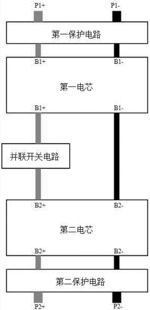
[0095] Such as image 3 As shown, in the embodiment of the present invention, the battery is improved and transformed into a controllable dual-parallel battery. The battery has a first connection port (P1+, P1-) and a second connection port (P2+, P2-), and the battery includes a first battery cell and a second battery cell connected in parallel and connected to the first battery cell and the second battery cell. Parallel switching circuit between cores. The parallel switching circuit can be connected to the positive connection path or the negative connection path of the first battery cell and the second battery cell, wherein the positive connection path is the connection path between the positive pole B1+ of the first battery cell and the positive pole B2+ of the second battery cell , the negative electrode connection path, that is, the connection path between the negative electrode B1- of the first cell and the negative electrode B2- of the second cell. The first cell is co...

Embodiment 2

[0154] refer to Figure 8 , a charging system according to a second embodiment of the present invention is proposed, the charging system includes a battery, a power supply module, a charging management module and a control module.

[0155] battery such as image 3 As shown, it has the first connection port (P1+, P1-) and the second connection port (P2+, P2-), and includes the first cell and the second cell connected in parallel and connected to the first cell and the second cell A parallel switching circuit between the cells, the first cell is connected to the first connection port (P1+, P1-), and the second cell is connected to the second connection port (P2+, P2-). The power supply module is connected to the first connection port (P1+, P1-) of the battery; the charging management module is connected to the second connection port (P2+, P2-) of the battery, and is connected to an external charger; the control module is respectively connected to the parallel switch circuit of ...


PUM


Abstract

The invention provides a charging method and a charging system. The charging method comprises the following steps: during charging, judging whether a first connecting port of a battery is being discharged or not; when the first connecting port is being discharged, judging whether the power consumption current is higher than a current threshold or not; when the power consumption current is higher than the current threshold, disconnecting a first battery core from a second battery core of the battery, and charging the battery through a second connecting port of the battery; when the power consumption current is lower than the current threshold, supplying power to the outside through a charging management module, controlling the first connecting port to stop discharge, connecting the first battery core with the second battery core, and charging the battery through the second connecting port; and when the first connecting port is not discharged, connecting the first battery core with the second battery core, and charging the battery through the second connecting port. Through the charging method and the charging system, a power consuming system connected with one connecting port and the charging management module connected with another connecting port are separated by the battery, so that local overheating caused by heat superposition of the two heat sources is avoided.

Description

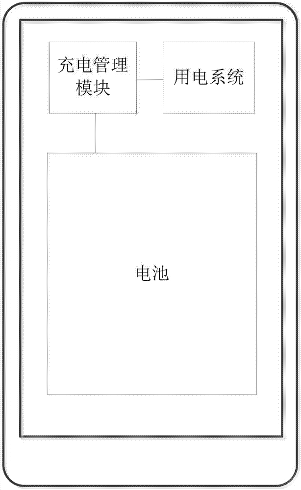
technical field [0001] The invention relates to the field of electronic technology, in particular to a charging method and a charging system. Background technique [0002] The charging system of existing mobile terminals such as mobile phones such as figure 1 As shown, it includes the battery and the charging management module. The battery has only one connection port. The charging management module is connected to the connection port, and the battery is charged through the connection port, and the battery is also discharged through the connection port. The charging management module is also connected to the charging system to supply power to the power consumption system. [0003] The layout structure of the charging system and the power system of the mobile terminal is generally as follows: figure 2 As shown, since the battery has only one connection port, both the charging management module and the power consumption system need to send or receive power through the same ...

Claims


Application Information

Patent Timeline
IPC IPC(8): H01M10/44H02J7/00
CPCH01M10/44H01M2010/4271H02J7/0068H02J7/0077Y02E60/10
Inventor 高秀文
Owner QIKU INTERNET TECH SHENZHEN CO LTD
Learn More