
3D printing equipment and printing method

A 3D printing and equipment technology, applied in the field of 3D printing, can solve problems such as the inability to judge the quality of the powder layer, reduce the performance of the product, and have a huge impact on performance, so as to avoid uneven powder coating and improve performance.

Active Publication Date: 2017-06-30
航天科工(长沙)新材料研究院有限公司
View PDF5 Cites 17 Cited by
  • Summary
  • Abstract
  • Description
  • Claims
  • Application Information

AI Technical Summary

Problems solved by technology

However, at present, the performance testing of metal powders for additive manufacturing still remains at the traditional parameter testing level. Using traditional powder material testing methods for characterization, the accuracy is not high, often resulting in the quality of the actual printed products not reaching the expected standard
[0005] During the research process, the applicant found that during the printing process of the product, the surface morphology of each layer of powder has a great influence on the performance of the printed product. The unevenness and defects caused by a certain layer of powder coating will cause a product defect, while Defects will further cause stress concentration and other effects, which will greatly reduce the performance of the product
However, when the existing 3D printing equipment is running, when there is a defect in a certain layer of powder coating, because the quality of the powder coating layer cannot be judged, it will generally continue to print, which will affect the performance of the product.

Method used


Image

  • 3D printing equipment and printing method
  • 3D printing equipment and printing method

Examples


Embodiment Construction

[0041] The present invention will be described in detail below with reference to the accompanying drawings and examples. It should be noted that, in the case of no conflict, the embodiments of the present invention and the features in the embodiments can be combined with each other. For the convenience of description, if the words "up", "down", "left" and "right" appear in the following, it only means that the directions of up, down, left and right are consistent with the drawings themselves, and do not limit the structure.

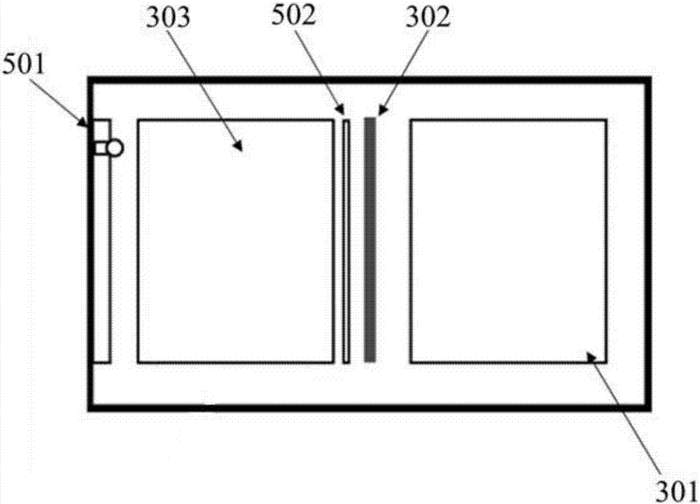
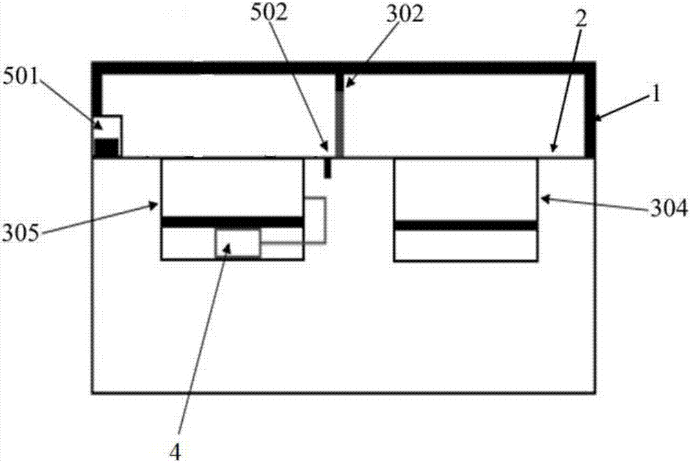
[0042] The 3D printing equipment of this embodiment includes a sealed casing 1, a working platform 2 parallel to the horizontal plane is arranged inside the casing 1, a powder spreading device is arranged inside the casing 1, and a powder spreading device is arranged around the powder spreading device. Surface topography measuring device; also includes a data processing device for processing the data obtained by the surface topography measuring device to ...


PUM


Abstract

The invention relates to 3D printing equipment and a printing method. The 3D printing equipment comprises a sealed shell body, a data processing device and a data feedback device. A power laying device is arranged in the shell body. A surface topography measuring device is arranged around the power laying device. The data processing device is used for processing data obtained by the surface topography measuring device, and a characteristic parameter of unevenness of the surface of a powder layer are obtained and compared with a set value. The data feedback device is used for receiving a data processing result of the data processing device and feeding back the data processing result to an operator. The feedback device is electrically connected with the data processing device. According to the 3D printing equipment and the printing method, the flatness of power laying layer can be monitored in real time in the printing process, it is convenient for the operator to reasonably adjust printing technology parameters, the product detect caused by nonuniform power laying is avoided, and accordingly the performance of the product is improved greatly.

Description

technical field [0001] The invention belongs to the technical field of 3D printing, and in particular relates to a 3D printing device and a printing method. Background technique [0002] 3D printing technology is a kind of rapid prototyping technology. It is based on a three-dimensional model, using metal powder or plastic and other bondable materials to construct three-dimensional three-dimensional parts by scanning layer by layer and stacking layer by layer. technology. This technology combines various disciplines such as CAD / CAM, optics, numerical control and material science, and has a wide range of applications. It has application prospects in jewelry, medical care, footwear, industrial design, architecture, aerospace, automobiles, education, etc. [0003] At present, for the 3D printing process of metal materials, SLM is the mainstream process. SLM technology is developed on the basis of SLS. The basic principles of the two are similar. SLM technology needs to comple...

Claims


Application Information

Patent Timeline
IPC IPC(8): B22F3/105B33Y10/00B33Y30/00
CPCB22F3/003B33Y10/00B33Y30/00B22F10/00B22F10/38B22F12/90B22F10/28Y02P10/25
Inventor 李晓庚
Owner 航天科工(长沙)新材料研究院有限公司
Learn More