Hydraulic cavitation generator for combined treatment of organic pollutants
A technology of organic pollutants and generators, which is applied in the research field of sewage cavitation treatment equipment to achieve the effect of improving treatment effect, improving degradation ability and expanding radiation range
- Summary
- Abstract
- Description
- Claims
- Application Information
AI Technical Summary
Problems solved by technology
Method used
Image
Examples
Embodiment 1
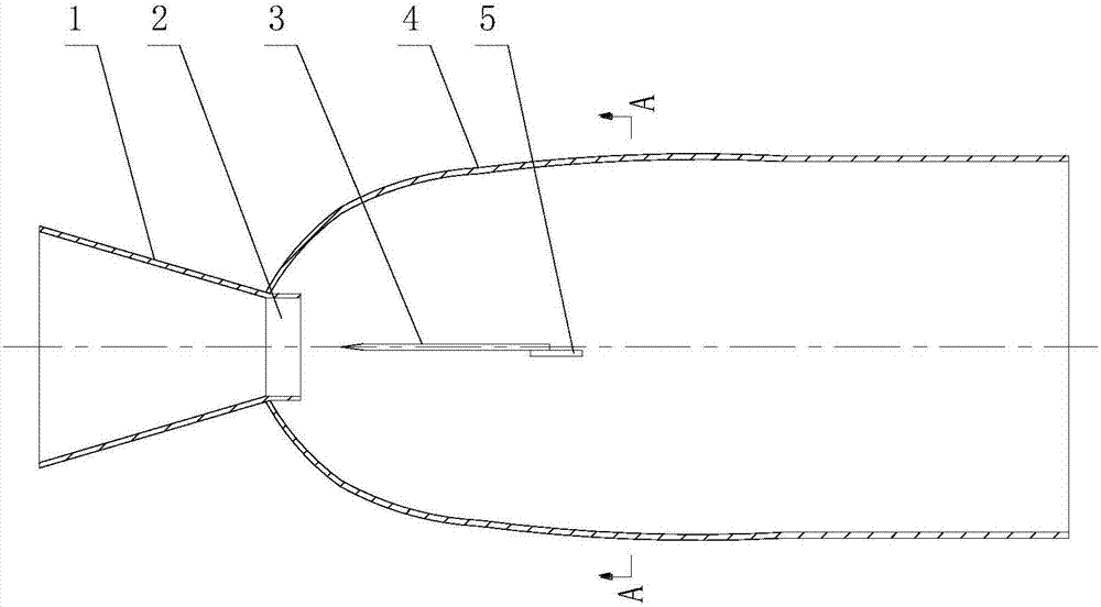
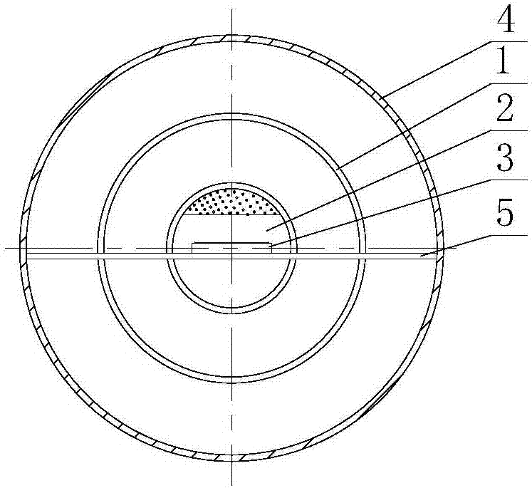
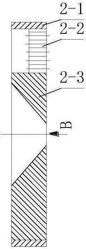
[0036] Depend on figure 1 with 2 It can be seen that the combined hydraulic cavitation generator for treating organic pollutants in this embodiment includes a water inlet pipe 1 , a combined cavitation head 2 , a reed 3 , a cavitation pipe 4 and a fixed plate 5 . Wherein, the inlet end of the water inlet pipe 1 communicates with the water inlet pump, the inner diameter of the inlet end is 60 mm, and the inner diameter of the outlet end is 48 mm. A cavitation pipe 4 is connected to the outlet end of the water inlet pipe 1, and a combined cavitation head 2 is installed at the junction of the water inlet pipe 1 and the cavitation pipe 4. The combined cavitation head 2 is composed of a cavitation sleeve 2-1, The perforated plate 2-2 is composed of the nozzle 2-3, the nozzle 2-3 and the perforated plate 2-2 are installed side by side in the inner cavity of the cavitation sleeve 2-1, and the cavitation sleeve 2-1 is welded to the outlet end of the water inlet pipe 1, It is connect...
Embodiment 2
[0046] Depend on Image 6 with 7 It can be seen that, in this embodiment, the inner diameter of the inlet end of the water inlet pipe 1 is 60 mm, and the inner diameter of the outlet end is 48 mm. A cavitation pipe 4 is connected to the outlet end of the water inlet pipe 1, and a combined cavitation head 2 is installed at the junction of the water inlet pipe 1 and the cavitation pipe 4. The combined cavitation head 2 is composed of a cavitation sleeve 2-1, The perforated plate 2-2 is composed of the nozzle 2-3, the nozzle 2-3 and the perforated plate 2-2 are installed side by side in the inner cavity of the cavitation sleeve 2-1, and the cavitation sleeve 2-1 is welded to the outlet end of the water inlet pipe 1, It is connected with the water inlet pipe 1 as a whole, and a perforated plate 2-2 and a nozzle 2-3 are installed side by side in the inner cavity of the cavitation sleeve 2-1, that is, the perforated plate 2-2 is a semicircular structure, occupying the space of the ...
Embodiment 3
[0057] Depend on Figure 8 with 9 It can be seen that, in this embodiment, the inner diameter of the inlet end of the water inlet pipe 1 is 60 mm, and the inner diameter of the outlet end is 48 mm. A cavitation pipe 4 is connected to the outlet end of the water inlet pipe 1, and a combined cavitation head 2 is installed at the junction of the water inlet pipe 1 and the cavitation pipe 4. The combined cavitation head 2 is composed of a cavitation sleeve 2-1, The perforated plate 2-2 is composed of the nozzle 2-3, the nozzle 2-3 and the perforated plate 2-2 are installed side by side in the inner cavity of the cavitation sleeve 2-1, and the cavitation sleeve 2-1 is welded to the outlet end of the water inlet pipe 1, It is connected with the water inlet pipe 1 as a whole, and a perforated plate 2-2 and a nozzle 2-3 are installed side by side in the inner cavity of the cavitation sleeve 2-1, that is, the perforated plate 2-2 is a semicircular structure, occupying the space of the...
PUM
| Property | Measurement | Unit |
|---|---|---|
| thickness | aaaaa | aaaaa |
| angle | aaaaa | aaaaa |
| radius | aaaaa | aaaaa |
Abstract
Description
Claims
Application Information
 - R&D
- Intellectual Property
- Life Sciences
- Materials
- Tech Scout
- Unparalleled Data Quality
- Higher Quality Content
- 60% Fewer Hallucinations
Browse by: Latest US Patents, China's latest patents, Technical Efficacy Thesaurus, Application Domain, Technology Topic, Popular Technical Reports.
© 2025 PatSnap. All rights reserved.Legal|Privacy policy|Modern Slavery Act Transparency Statement|Sitemap|About US| Contact US: help@patsnap.com


