Measurement method of transition position of airfoil surface boundary layer based on distributed thermosensitive optical fiber

A measurement method and distributed technology, applied in the direction of measuring devices, measuring heat, thermometers, etc., can solve the problems of deviation of test results, influence of aerodynamic shape, etc., and achieve the effect of improved spatial accuracy, convenient judgment method, and high spatial measurement accuracy

Active Publication Date: 2017-06-30
NORTHWESTERN POLYTECHNICAL UNIV
View PDF3 Cites 14 Cited by
  • Summary
  • Abstract
  • Description
  • Claims
  • Application Information

AI Technical Summary

Problems solved by technology

Traditional temperature measurement methods such as thermocouples and platinum resistance thermometers can achieve single-point temperature testing, but if they are fixed on the skin or model surface, they will have a great impact on the aerodynamic shape; recently developed infrared thermometers and thermal imagers can achieve

Method used


Image

  • Measurement method of transition position of airfoil surface boundary layer based on distributed thermosensitive optical fiber
  • Measurement method of transition position of airfoil surface boundary layer based on distributed thermosensitive optical fiber
  • Measurement method of transition position of airfoil surface boundary layer based on distributed thermosensitive optical fiber

Examples


Embodiment Construction

[0048] This embodiment is a method for measuring surface flow transition based on distributed temperature-sensitive optical fibers.

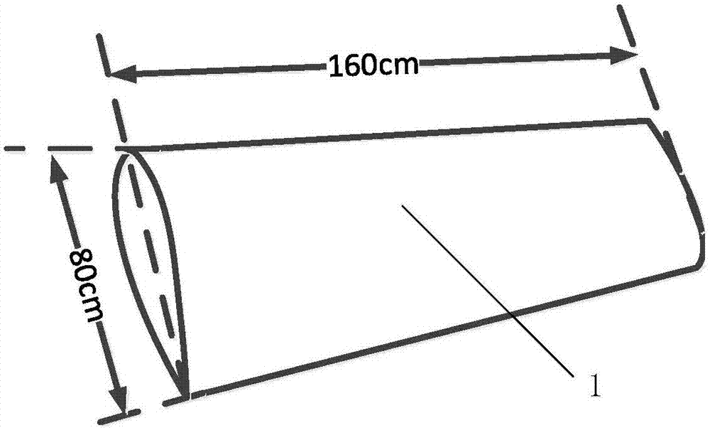
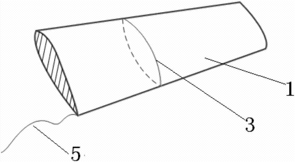
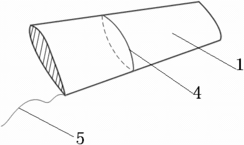
[0049] The optical fiber used in this embodiment is the temperature optical fiber 4 . The optical fiber in the temperature optical fiber 4 casing only feels the temperature change, which can effectively eliminate the problem of thermal coupling. The airfoil model 1 used is attached figure 1 As shown, it is made of aluminum alloy.

[0050] The concrete implementation process of this embodiment:

[0051] Step 1, airfoil model installation:

[0052] The airfoil model 1 is installed in the wind tunnel 7 according to the conventional method, and is fixedly connected with the lower turntable 2 of the wind tunnel, as attached figure 2 shown. The angle of attack of the airfoil model 1 can be adjusted by turning the lower turntable 2 of the wind tunnel.

[0053] Step 2, laying optical fiber:

[0054] Use an optical fiber cutting machine to cut ou...


PUM


Abstract

The invention discloses a measurement method of a transition position of airfoil surface boundary layer based on a distributed thermosensitive optical fiber. The method comprises the steps of laying a temperature optical fiber on the surface of an airfoil model, and measuring the temperature distribution of airflow flowing through the surface of an object through a distributed thermosensitive optical fiber to judge a flow transition position. Back Rayleigh scattering light in the optical fiber is measured through a backlight reflexometer, and after loss and optical fiber length information are obtained and a sensing module is added, a common monomode optical fiber serving as a sensor can be used to perform temperature low-frequency testing reaching 1cm space resolution and 0.1-DEG C temperature resolution within a 70m range. Compared with other transition measurement technology, both the temperature resolution and the special accuracy judged by transition position are enhanced. The method has the advantages that a dynamic pressure sensor is not required to be embedded on the surface of an object for judging transition through dynamic pressure, the method is easier to realize than wall shear stress measurement and transition measurement judgment method through a thermal infrared imager, and the spatial resolution is high.

Description

technical field [0001] The invention relates to an object surface flow transition measurement technology, in particular to a method for judging the flow transition position by using a distributed temperature-sensitive optical fiber to measure the temperature distribution of the airflow flowing through the object surface. Background technique [0002] Transition is the transition process of the fluid boundary layer on the surface of the object from laminar flow to turbulent flow. The transition problem of the fluid boundary layer is still one of the difficult problems in the study of fluid mechanics. The transition process is very complex, including destabilization of layers, appearance and amplification of T-S wave, development of three-dimensional disturbance and formation of flow vortex, high-frequency oscillation and turbulent spot caused by secondary destabilization of flow, expansion of turbulent spot and development into complete turbulence A series of complex unsteady...

Claims


Application Information

Patent Timeline
IPC IPC(8): G01N11/00G01K11/32
CPCG01K11/32G01N11/00G01N2011/0093
Inventor 焦予秦赵越肖春生陈碧华
Owner NORTHWESTERN POLYTECHNICAL UNIV
Why Eureka
Try Eureka