Optimal setting method for relationship curve of emulsion flow and rolling speed in cold rolling process

A rolling speed and optimization setting technology, applied in the field of metallurgy, can solve problems such as the inability to meet the high-precision control of emulsion

Active Publication Date: 2017-06-30
YANSHAN UNIV
View PDF12 Cites 30 Cited by
  • Summary
  • Abstract
  • Description
  • Claims
  • Application Information

AI Technical Summary

Problems solved by technology

However, the relevant researches are almost all carried out around the setting of the emulsion flow rate under the constant speed state, and the setting of the emulsion flow rate in the cold rolling process in the field is mostly constant (that is, al

Method used


Image

  • Optimal setting method for relationship curve of emulsion flow and rolling speed in cold rolling process
  • Optimal setting method for relationship curve of emulsion flow and rolling speed in cold rolling process
  • Optimal setting method for relationship curve of emulsion flow and rolling speed in cold rolling process

Examples


Embodiment 1

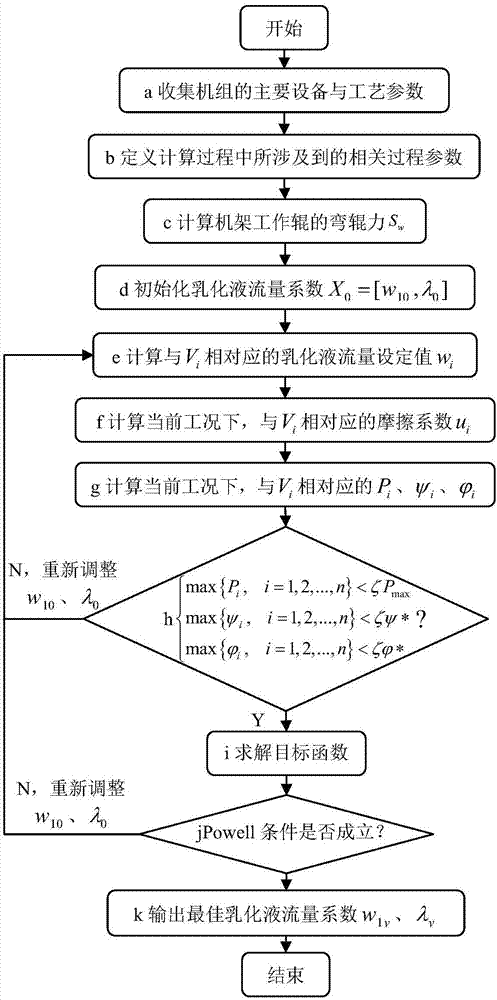
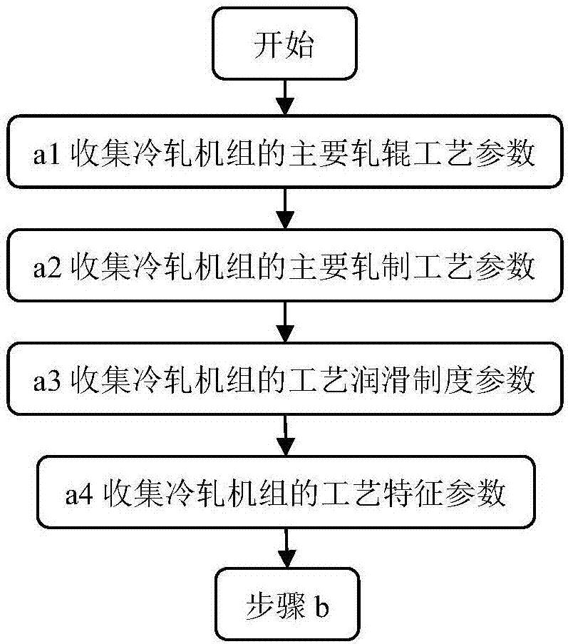
[0037] according to figure 1 The overall flow chart for the calculation of the optimal setting method for the relationship curve between the emulsion flow and the velocity is shown. First, in step a, the main equipment and process parameters of the cold rolling mill are collected, which mainly includes the following steps (such as figure 2 shown):

[0038] In step a1, the roll process parameters of the cold rolling mill are collected, mainly including: work roll radius R=211.80mm, surface roughness Ra r =0.48μm, the elastic modulus E of the work roll=206GPa, the Poisson’s ratio ν=0.3 of the work roll;

[0039] Subsequently, in step a2, the rolling process parameters of the cold rolling mill are collected, mainly comprising: the average deformation resistance K of the strip m =460MPa, strip width B=850mm, incoming material thickness h 0 =2.00mm, reduction rate ε j ={44.3,44.2,38.1,32.5,19.3}%, the maximum rolling speed V max =1228.5m / min, rolling pressure setting value P=...

Embodiment 2

[0063] First, in step a, the main equipment and process parameters of the cold rolling mill are collected, which mainly includes the following steps:

[0064] In step a1, the roll process parameters of the cold rolling mill are collected, mainly including: work roll radius R=201.94mm, surface roughness Ra r =0.52μm, the elastic modulus E of the work roll=206GPa, the Poisson’s ratio ν=0.3 of the work roll;

[0065] Subsequently, in step a2, the rolling process parameters of the cold rolling mill are collected, mainly comprising: the average deformation resistance K of the strip m =520MPa, strip width B=750mm, incoming material thickness h 0 =2.50mm, reduction rate ε j ={43.9,43.8,37.6,32.0,16.3}%, the maximum rolling speed V max =1402.5m / min, rolling pressure setting value P=6500kN, front tension σ 1 =162.9MPa, back tension σ 0 =60.6MPa;

[0066] Subsequently, in step a3, process lubrication system parameters are collected, mainly including emulsion concentration C=3.7%, ...


PUM


Abstract

Provided is an optimal setting method for the relationship curve of the emulsion flow and the rolling speed in the cold rolling process. The method mainly comprises the following steps: 1, collecting main equipment and process parameters of a cold rolling unit; 2, defining the process parameters involved in the optimization process of the emulsion flow; 3, calculating the roll bending force of a rack working roll; 4, initializing the emulsion flow coefficient; 5, calculating the set value of the emulsion flow corresponding to Vi; 6, calculating the friction coefficient mui corresponding to Vi; 7, calculating the rolling pressure, slipping factor and thermal slipping injury index corresponding to Vi; 8, solving the objective function; 9, outputting the best emulsion flow coefficient, and determining the relationship curve of the best emulsion flow and speed. The method has the advantages that the overall fluctuation rate and the maximum fluctuation rate of the rolling pressure can be kept smaller during the speed-up and speed-down process, and it is ensured that the slipping and thermal slipping defects are prevented from occurring in the rolling process, thus the surface quality and the strip shape control precision of strip steels are improved.

Description

technical field [0001] The invention belongs to the technical field of metallurgy, in particular to a method for cold rolling a strip. Background technique [0002] In recent years, with the development of the modern sheet metal processing industry towards high automation and the wider use of cold-rolled strip, it is imperative to improve the efficiency of the unit and the quality of the finished product. At the same time, as steel enters the era of "mean profits", the market competition in the strip industry around quality is also becoming increasingly fierce. In the cold rolling production process, the setting of the relationship curve between the emulsion flow rate and the rolling speed plays a decisive role in the control of product quality. If the setting of the relationship curve between emulsion flow and rolling speed in the cold rolling process is unreasonable, it may cause the following consequences: (1) The rolling pressure fluctuates too much during the speed-up ...

Claims


Application Information

Patent Timeline
IPC IPC(8): G06F17/50G06Q10/04G06Q50/04B21B37/44
CPCB21B37/44G06F30/20G06Q10/04G06Q50/04Y02P90/30
Inventor 白振华王松尧赵伟泉李柏阳邢雨刘亚星
Owner YANSHAN UNIV
Why Eureka
Try Eureka