
A Phased Array Antenna with Large Element Spacing Based on Subarray

A phased array antenna and unit spacing technology, which is applied in the directions of individually powered antenna arrays, antennas, antenna arrays, etc., can solve the problems of not seeing complete reports, increasing antenna cross-polarization, and different unit spacing, etc. The effect of reduced design difficulty, reduced clearance, good and poor performance

Active Publication Date: 2020-04-07
CHINA ELECTRONIC TECH GRP CORP NO 38 RES INST
View PDF5 Cites 2 Cited by
  • Summary
  • Abstract
  • Description
  • Claims
  • Application Information

AI Technical Summary

Problems solved by technology

When the rotation angle is too large, the cross-polarization of the antenna will be increased, and the gap between the sub-arrays will be large, which will affect the side lobes
In China, Zhu Ruiping proposed to use a ring grid structure and a sub-array sub-box structure to suppress the grid lobes, but there are many types of sub-arrays. In order to facilitate the connection with the back-end transceiver components, the component modules also need to be made into various specifications.
Wang Xin et al. proposed a sub-array arrangement method that gradually thins from the middle to the edge to suppress grating lobes, but the cell spacing between the middle sub-array and the edge sub-array is different, and it is still necessary to design two corresponding transceiver module modules
In recent years, many scholars have proposed to use different optimization algorithms to give the position arrangement of non-periodic sub-arrays, but no complete reports have been seen yet.

Method used


Image

  • A Phased Array Antenna with Large Element Spacing Based on Subarray
  • A Phased Array Antenna with Large Element Spacing Based on Subarray
  • A Phased Array Antenna with Large Element Spacing Based on Subarray

Examples


Embodiment Construction

[0023] The embodiments of the present invention are described in detail below. This embodiment is implemented on the premise of the technical solution of the present invention, and detailed implementation methods and specific operating procedures are provided, but the protection scope of the present invention is not limited to the following implementation example.

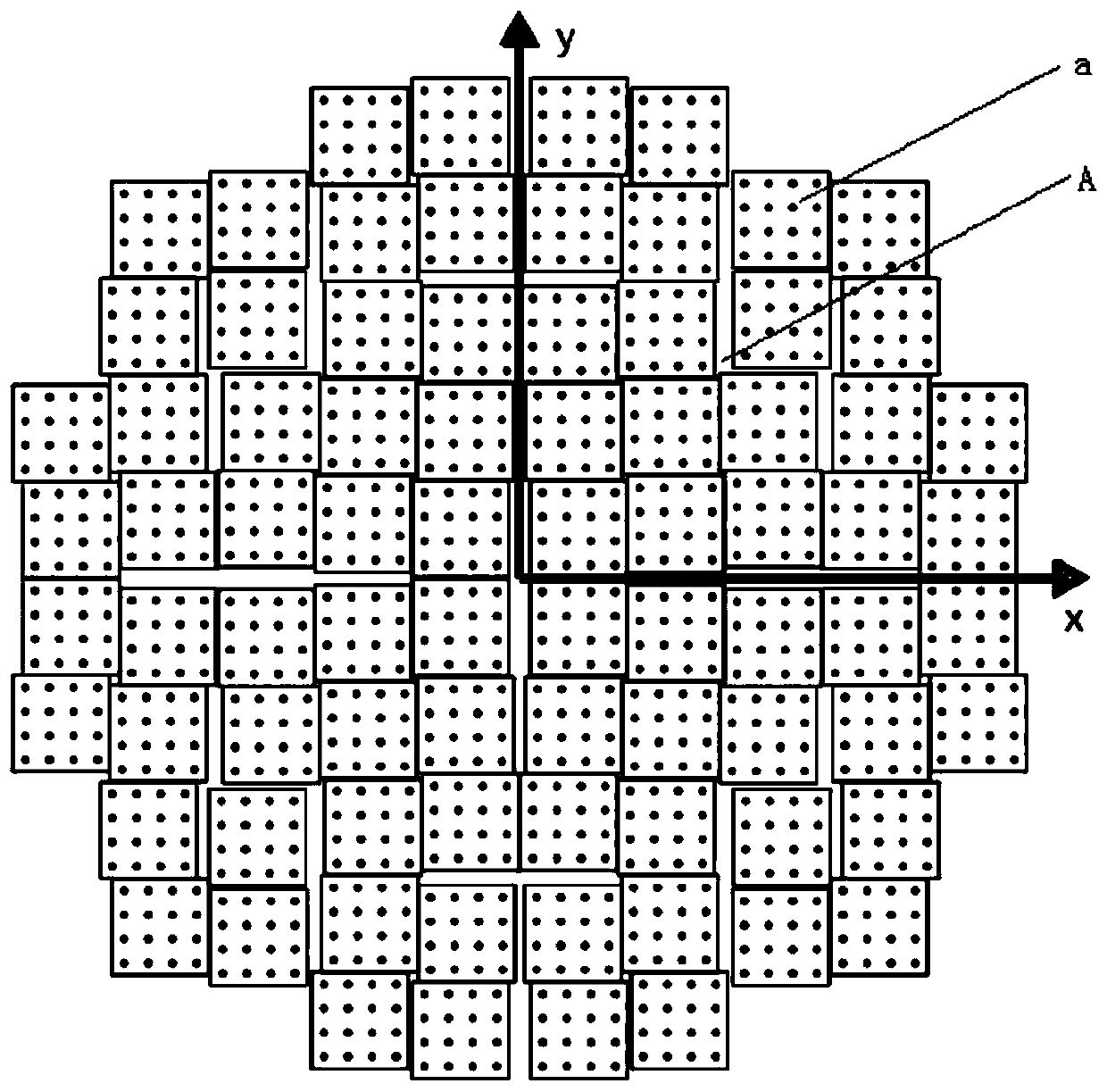
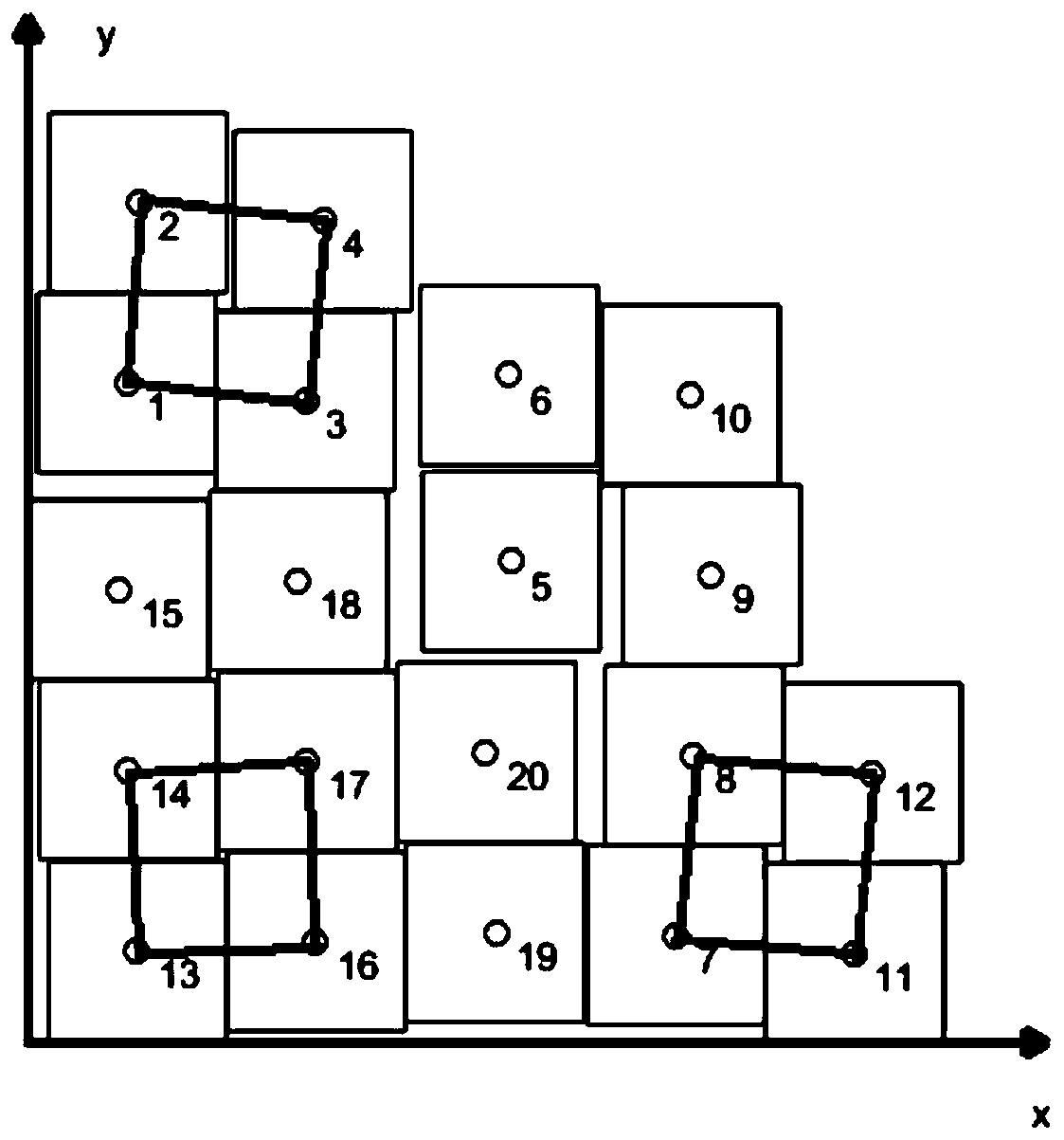
[0024] like figure 1 and figure 2 As shown, the array of the antenna in this embodiment is divided into the first, second, third and fourth quadrants according to the Cartesian coordinate system, and the four quadrants of the first, second, third and fourth quadrants are about the quadrant center Clockwise rotational symmetry to form a sum-difference beam, the first quadrant A includes 20 non-periodically arranged sub-arrays a, the line connecting the centers of the sub-arrays a in the same row or column is a curve, and each A sub-array a includes 16 units. The entire array has 80 (4*20) sub-arrays a and 1280 (...


PUM


Abstract

The invention discloses a big-unit-interval phased array antenna based on a subarray level. The array surface of the antenna is divided into four quadrants according to a rectangular coordinate system: a first quadrant, a second quadrant, a third quadrant, and a fourth quadrant, wherein the four quadrants are in clockwise rotational symmetry relative to a quadrant center. The first quadrant comprises a plurality of aperiodic subarrays, wherein the connection line of the centers of the subarrays which are located in the same line or same column, and each subarray comprises a plurality of units. Through combining with the array aperiodic principle, an array with the unit interval being greater than one wavelength is constructed. Based on a modular idea, the antenna meets the requirements of gain, minor lobe and grating lobe inhibition through a fewer antenna units and a smaller number of subarrays, and reduces the cost of an antenna system. The antenna effectively reduces the interval between the subarrays, guarantees the aperiodic arrangement of the subarrays, effectively inhibits the grating lobe level, does not need to rotate the subarrays, does not increase the cross polarization level, and enables the minor lobe level not to decrease too much.

Description

technical field [0001] The invention relates to a structure of a phased array antenna, in particular to a phased array antenna with a large element spacing based on a sub-array level. Background technique [0002] Phased array antennas usually arrange the same antenna elements in both horizontal and vertical directions to form an area array to achieve two-dimensional beam scanning. Low sidelobes and arbitrary pointing are achieved through independent control of the amplitude and phase excitation of each radiating antenna. When arranging the antenna elements, if the element spacing is greater than one wavelength, unnecessary grating lobes will be formed in the pattern; if it is too small, the mutual coupling of the array elements will increase, which will affect the performance of the antenna. Increase the number of units. [0003] In order to reduce costs, it is generally desired to reduce the number of units and the number of transceiver components as much as possible und...

Claims


Application Information

Patent Timeline
Patent Type & Authority Patents(China)
IPC IPC(8): H01Q21/00H01Q21/20
CPCH01Q21/00H01Q21/20
Inventor 翟永波王小陆卢晓鹏郑林华
Owner CHINA ELECTRONIC TECH GRP CORP NO 38 RES INST
Features
  • Generate Ideas
  • Intellectual Property
  • Life Sciences
  • Materials
  • Tech Scout
  • Unparalleled Data Quality
  • Higher Quality Content
  • 60% Fewer Hallucinations
Learn More