
Rock property test system and rock damage evolution test method

A technology for testing systems and rock properties, applied in measuring devices, material analysis using acoustic wave emission technology, instruments, etc., can solve the problems of limited applicability, high research costs, discrete macroscopic mechanical behavior, etc., and achieve the goal of overcoming geometric shapes Effects of restrictions, reliable method support, and low research costs

Inactive Publication Date: 2017-07-04
HOHAI UNIV
View PDF4 Cites 31 Cited by
  • Summary
  • Abstract
  • Description
  • Claims
  • Application Information

AI Technical Summary

Problems solved by technology

The development of research on the damage evolution mechanism of rock-like solid materials is extremely slow. First, there is a lack of reliable mesoscopic damage quantification methods. Second, the complexity of the internal structure of rock-like materials and the discreteness of macroscopic mechanical behavior
[0003] The development of rock micro-optical testing machine has effectively promoted the quantitative study of mesoscopic damage. Through the quantitative description of the apparent damage evolution of the rock during the loading process, the relationship between the apparent damage amount and the macroscopic mechanical properties has been discussed. However, such methods It can only observe the damage evolution process of the rock surface, but cannot reflect the internal fracture mechanism
At the same time, with the development of rock-like materials, transparent rock materials with high brittleness are more and more widely used in damage evolution. Traditional rock optical testing machines have higher requirements on the geometry of transparent rock materials, that is, samples should not be made into Conventional three-axis cylindrical sample, because the cylindrical transparent sample is not conducive to the observation of the telephoto camera
Even the introduction of CT technology is limited in its applicability due to its high research cost

Method used


Image

  • Rock property test system and rock damage evolution test method
  • Rock property test system and rock damage evolution test method

Examples


Embodiment Construction

[0033] The present invention will be further explained below in conjunction with the accompanying drawings and specific embodiments.

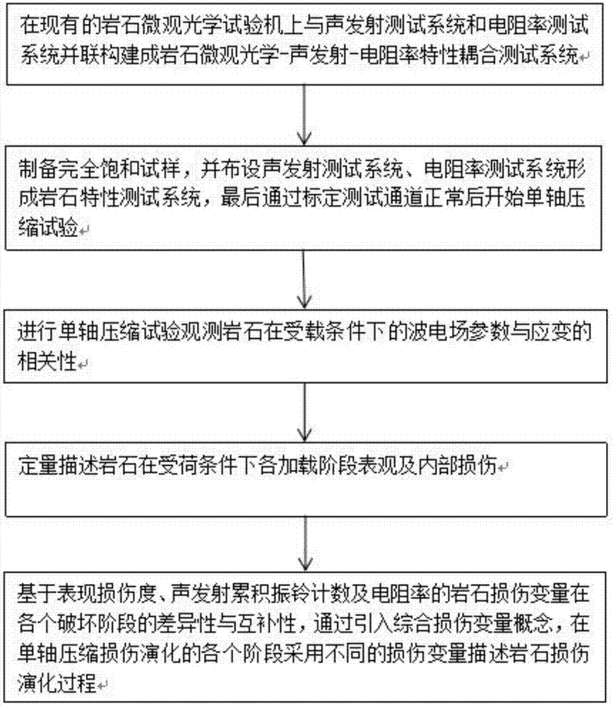
[0034] Such as figure 2 As shown, the rock damage evolution test method of the present invention is carried out successively according to the following steps:

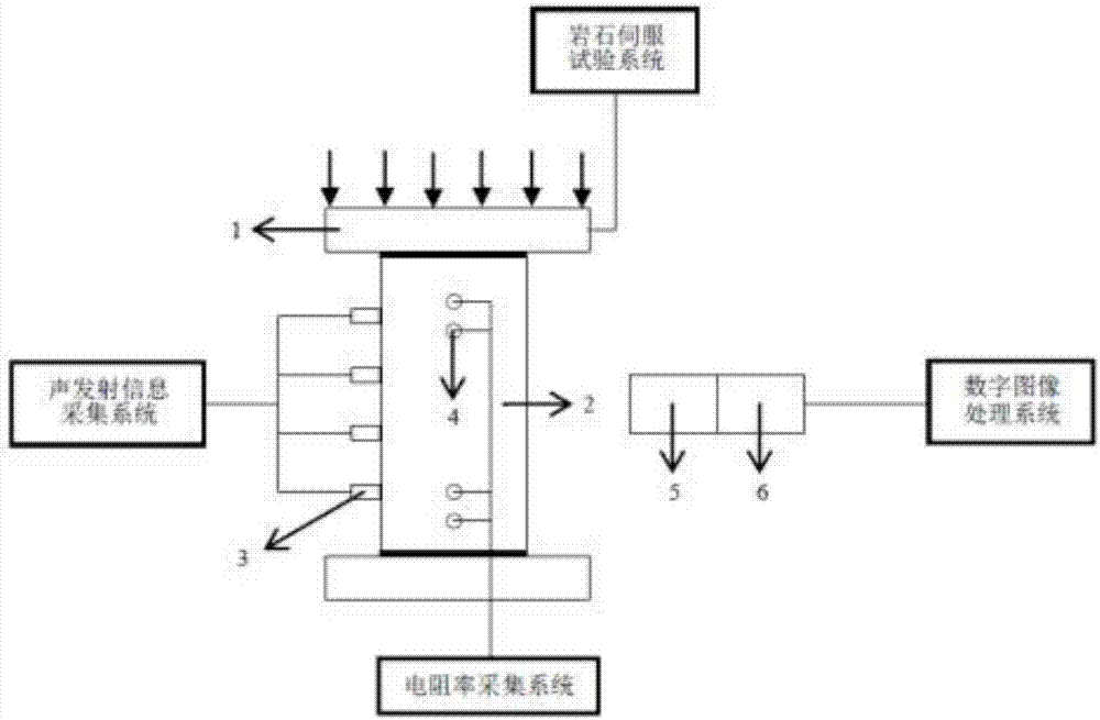
[0035] (1) Construct a rock micro-optics-acoustic emission-resistivity characteristic coupling test system. On the basis of the existing micro-optics testing machine, connect the PCI-8 rock acoustic emission test system and the V8 rock resistivity test system in parallel. The acoustic emission test The system and the resistivity test system are both high-speed sensitive real-time data acquisition systems, which can measure the changes in acoustic emission parameters and resistivity at the moment of rock fracture. The working frequency of the system is about 1.0kHz ~ 2.4MHz.

[0036] (2) A granite core sample with a height of 100mm and a diameter of 50mm was drilled indoors. Both ends...


PUM

PropertyMeasurementUnit
Diameteraaaaaaaaaa
Heightaaaaaaaaaa

Abstract

The invention discloses a rock property test system, which comprises a rock microscopic optical tester. A fully saturated sample is placed on the rock microscopic optical tester, and the surface of the fully saturated sample is provided with an acoustic emission test system and a resistivity test system. Specifically, a rock damage evolution test method includes the steps of: 1. connecting the rock microscopic optical tester with the acoustic emission test system and the resistivity test system in parallel; 2. assembling a rock property test system; 3. performing uniaxial compression test and observing the correlation of the rock's wave electric field parameters and strain under a loaded condition; 4. quantitatively describing the appearance and internal injury of the rock at each loading stage under a load-bearing condition; and 5. at each stage of uniaxial compression damage evolution, employing different damage variables to describe the rock damage evolution process. The system and the method provided by the invention can realize whole course observation of the whole process of the rock internal and external damage rupture, and overcomes the restriction of traditional testers on the sample shape.

Description

technical field [0001] The invention belongs to the technical field of rock mechanics and geology, and in particular relates to a rock characteristic testing system and a rock damage evolution testing method thereof. Background technique [0002] Engineering rocks often contain a large number of tiny cracks and micro-cavities. At the same time, the loss and fracture process of rocks under load is often a process of microscopic damage expansion and evolution, and macroscopically shows a staged stress-strain curve. The development of research on the damage evolution mechanism of rock-like solid materials is extremely slow. First, there is a lack of reliable mesoscopic damage quantification methods. Second, the complexity of the internal structure of rock-like materials and the discreteness of macroscopic mechanical behavior. [0003] The development of rock microscopic optical testing machine has effectively promoted the quantitative research of mesoscopic damage. Through the ...

Claims


Application Information

Patent Timeline
IPC IPC(8): G01N27/04G01N29/14
CPCG01N27/041G01N29/14G01N2291/0232G01N2291/0289
Inventor 孔洋朱珍德阮怀宁石崇张聪卢文斌
Owner HOHAI UNIV
Learn More