
Special fixture for long shaft

A special fixture and long-axis technology, which is applied in the field of processing and manufacturing, can solve the problems of unfavorable factory quality goals and profit goals, the inability to completely offset the bending stress of the long-axis, and high scrap pressure, so as to achieve good clamping stability and reliability. Broad application prospects and promotion value, the effect of improving production efficiency

Inactive Publication Date: 2017-07-07
天津鑫泰博弈科技有限公司
View PDF0 Cites 9 Cited by
  • Summary
  • Abstract
  • Description
  • Claims
  • Application Information

AI Technical Summary

Problems solved by technology

However, the existing long-axis special fixtures are usually directly set in the middle of the workpiece. Although the ratio of the length to diameter of the long-axis can be reduced by half, the rigidity of the long-axis can be improved to a certain extent, and the machining accuracy can be improved, but the long-axis cannot be completely offset. The bending stress generated by its own gravity and the partial gravity at the end of the long axis will also affect the straightness of the entire axis. Bad phenomena still occur frequently, and the scrap pressure that the factory needs to bear and absorb is still relatively large, so it will cause a certain degree of economic loss. , which is not conducive to the achievement of the factory's quality goals and profit goals. Therefore, a special long-axis fixture with reasonable clamping, high clamping stability, and good processing quality needs to be launched urgently.

Method used


Image

  • Special fixture for long shaft

Examples


Embodiment Construction

[0015] The present invention will be described in further detail below in conjunction with the accompanying drawings and preferred embodiments.

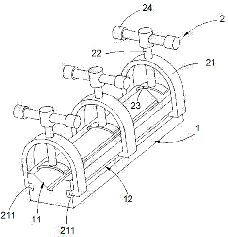
[0016] figure 1 It is a schematic diagram of a preferred embodiment of a long-axis special clamp provided by the present invention. Such as figure 1 As shown, the material of the special fixture for the long axis is stainless steel with excellent performance, which specifically includes a support 1 and three fasteners 2, wherein the top of the support 1 is provided with a centered, end-to-end V-shaped groove 11 , The two side walls of the support 1 are symmetrically provided with two guide rail grooves 12 penetrating from end to end. The cross-sectional shape of the guide rail groove 12 is rectangular, which is convenient for processing and forming. The three fasteners 2 are evenly arranged at the front, middle and rear ends of the support 1 along the direction of the guide rail groove, which can restrain the deformation of each pa...


PUM


Abstract

The invention discloses a special fixture for a long shaft. The special fixture comprises a support and a plurality of fastening pieces; a V-shaped groove formed in the middle and perforated from the head to the end is formed in the top of the support; two guide rail grooves perforated from the heads to the ends are symmetrically formed in the two side walls of the support; the fastening pieces are arranged on the support in the directions of the guide rail grooves in a uniformly spaced manner; each fastening piece comprises a bracket, an adjustment rod and a clamping plate; each bracket is provided with two sliding blocks, and is arranged in the guide rail grooves in the two sides of the support through the corresponding two sliding blocks; and the clamping plates are arranged above the V-shaped groove and are movably connected with the brackets through the adjustment rods. Compared with the prior art, through rational design the structure of the fixture, the long shaft is clamped more reasonably in a machining process, the clamping stability and the reliability are better, the machining quality of the long shaft is improved effectively, a reject rate of a production line is reduced to the lowest, the special fixture is simple in structure and extremely convenient to disassemble and assemble, the time and labor are saved, the production efficiency is improved effectively, and higher economic benefits are generated. Therefore, the special fixture has very broad application prospects.

Description

technical field [0001] The invention relates to a clamp, in particular to a special clamp for a long axis, and belongs to the technical field of processing and manufacturing. Background technique [0002] The long shaft is a common mechanical part. In production, it is customary to call the workpiece with a ratio of length to diameter greater than 10 to 20 times the long shaft. Due to the poor rigidity of the long shaft itself, it is prone to bending during processing, which seriously affects Machining accuracy such as cylindricity, concentricity, and surface roughness has a high defect rate and poor economic benefits. Therefore, special fixtures are usually used in production to clamp and fix the long axis, which can effectively reduce the defect rate. However, the existing long-axis special fixtures are usually directly set in the middle of the workpiece. Although the ratio of the length to diameter of the long-axis can be reduced by half, the rigidity of the long-axis can...

Claims


Application Information

Patent Timeline
Patent Type & Authority Applications(China)
IPC IPC(8): B23Q3/06
CPCB23Q3/064B23Q3/069
Inventor 曹润星杨振勇李卫华
Owner 天津鑫泰博弈科技有限公司
Features
  • Generate Ideas
  • Intellectual Property
  • Life Sciences
  • Materials
  • Tech Scout
  • Unparalleled Data Quality
  • Higher Quality Content
  • 60% Fewer Hallucinations
Learn More