Ultraviolet LED device

A technology of LED device and LED chip, applied in the field of ultraviolet LED, can solve the problems of low reliability, poor heat dissipation, short life and so on

Pending Publication Date: 2017-07-07
GUANGDONG UNIV OF TECH
View PDF11 Cites 17 Cited by
  • Summary
  • Abstract
  • Description
  • Claims
  • Application Information

AI Technical Summary

Problems solved by technology

[0004] The object of the present invention is to provide an ultraviolet LED device, aiming to solve the prob...

Method used


Image

  • Ultraviolet LED device
  • Ultraviolet LED device
  • Ultraviolet LED device

Examples


Embodiment Construction

[0021] In order to make those skilled in the art better understand the solution of the present invention, the present invention will be further described in detail below with reference to the accompanying drawings and specific embodiments. Obviously, the described embodiments are only some, but not all, embodiments of the present invention. Based on the embodiments of the present invention, all other embodiments obtained by those of ordinary skill in the art without creative efforts shall fall within the protection scope of the present invention.

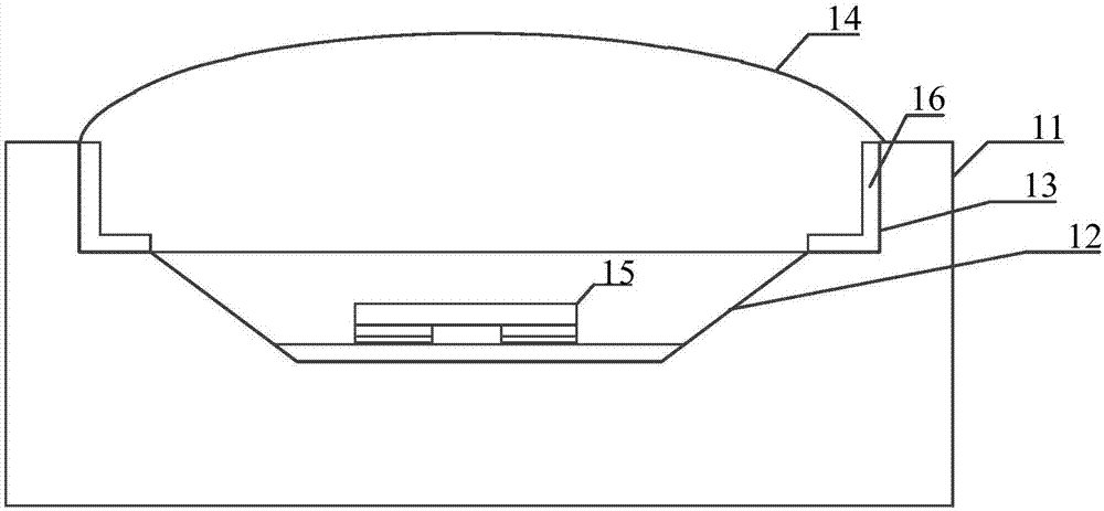
[0022] See figure 1 , figure 1 It is a schematic structural diagram of the ultraviolet LED device provided by the embodiment of the present invention. The device includes a ceramic base 11; a groove 12 disposed on the ceramic base; a groove 12 disposed on the ceramic base and located on the groove A mesa-shaped stepped structure 13; a quartz glass cover plate 14 installed at the mesa-shaped stepped structure; an ultraviolet LED ch...


PUM

PropertyMeasurementUnit
Thicknessaaaaaaaaaa
Thicknessaaaaaaaaaa

Abstract

The present invention discloses an ultraviolet LED device, which comprises a ceramic base, a groove arranged on the ceramic base, a table-shaped stepped structure arranged on the ceramic base and positioned on the groove, a quartz glass cover plate arranged at the table-shaped stepped structure, and an ultraviolet LED chip welded to the bottom surface of the groove in the eutectic flip-chip manner. At least two metal layers, good in heat conductivity and electrical conductivity, are arranged between the positive and negative electrodes of the ultraviolet LED chip and the bottom surface of the groove. In this way, the eutectic flip welding of the ultraviolet LED chip is realized. According to the invention, through the metal layers good in heat conductivity and electrical conductivity, the ultraviolet LED chip is welded inside the ultraviolet LED device in the eutectic flip-chip manner. Therefore, the application of the traditional solid crystal organic glue is avoided. Meanwhile, on the premise that the electrical connection of the ultraviolet LED chip is ensured, the heat is conducted to the ceramic base. The heat conductivity of the device is improved, so that the stability and the service life of the device are increased. As a result, according to the technical scheme of the invention, the heat dissipation performance of the ultraviolet LED device is improved.

Description

technical field [0001] The invention relates to the field of ultraviolet LEDs, in particular to an ultraviolet LED device. Background technique [0002] Ultraviolet LED is a kind of LED. It has the advantages of ultra-long life, cold light source, no thermal radiation, life is not affected by the number of times of opening and closing, high energy, high uniform irradiation efficiency, and no toxic substances, making it suitable for medical treatment, sterilization, etc. , printing, lighting, data storage and secure communications have greater application value. [0003] As the wavelength of the LED becomes shorter and the radiant energy becomes stronger, the UV resistance of the traditional organic packaging material drops sharply, which in turn leads to a shorter lifespan and lower stability of the UV LED. And the high energy of UV LED radiation will generate a lot of heat, and the traditional packaging method cannot meet the heat dissipation requirements. SUMMARY OF THE...

Claims


Application Information

Patent Timeline
IPC IPC(8): H01L33/48H01L33/62H01L33/64
CPCH01L33/486H01L33/62H01L33/641H01L33/647
Inventor 何苗黄波周俊楠王志成王成民
Owner GUANGDONG UNIV OF TECH
Why Eureka
Try Eureka