

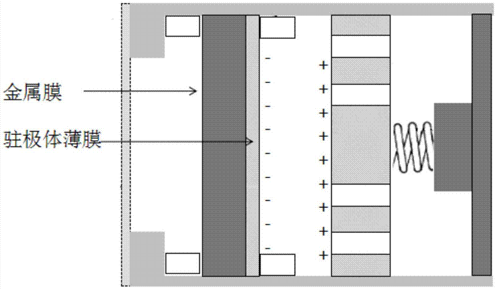
Capacitive sound acquisition device and microphone
A sound collection device and capacitive technology, applied in the field of microphones, can solve the problems of consumer electronics inconvenience, large polarization voltage, and low sensitivity, and achieve the effects of compact overall structure, good tension performance, and wide frequency characteristics
- Summary
- Abstract
- Description
- Claims
- Application Information
AI Technical Summary
Problems solved by technology
Method used
Image

Examples
Embodiment 1
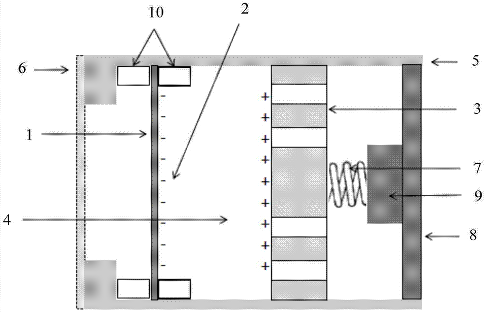
[0025] In a specific embodiment, such as figure 2 As shown, the microphone has a housing 5, and the capacitive sound collection device is inside the housing. The graphene diaphragm 1 is pre-polarized and has a resident charge 2, so that the air between the graphene diaphragm 1 and the back electrode 3 A prepolarization electric field 4 is formed in the gap, and the potential of this electric field is generally 200-300 volts.
[0026] One side of the shell 5 is open and covers the dust cover 6 , and the graphene diaphragm 1 is located between the dust cover 6 and the back electrode 3 . The back electrode 3 is connected to the field effect transistor 9 on the circuit board 8 through the spring 7 .
[0027] Further, a deck 10 is provided on the inner wall of the housing 5 , and the graphene diaphragm 1 is fixed on the deck 10 .
[0028] The prepolarized graphene diaphragm 1 can be obtained by redox method, ultrasonic stripping ion adsorption method and other methods. The spec...
Embodiment 2
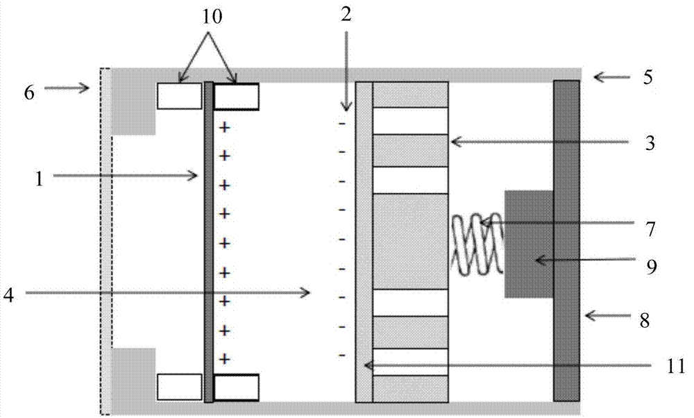
[0038] In another specific embodiment, such as image 3 As shown, the microphone has a housing 5, the capacitive sound collection device is inside the housing, and the side of the back electrode 3 facing the graphene diaphragm 1 (30 layers) covers the electret layer 11. The electret layer 11 carries resident charges 2, and a prepolarization electric field 4 is generated in the air gap between the electret layer 11 and the graphene diaphragm 1, and the electric field potential is about 200-300 volts at this time.
[0039] One side of the shell 5 is open and covers the dust cover 6 , and the graphene diaphragm 1 is located between the dust cover 6 and the back electrode 3 . The back electrode 3 is connected to the field effect transistor 9 on the circuit board 8 through the spring 7 . A deck 10 is provided on the inner wall of the housing 5 , and the graphene diaphragm 1 is fixed on the deck 10 .
[0040]The material of the electret layer 11 can be but not limited to Teflon, p...
Embodiment 3
[0044] In another specific embodiment, such as Figure 4 As shown, the microphone has a housing 5, the capacitive sound collection device is inside the housing 5, and the side of the graphene diaphragm 1 (30 layers) facing the back electrode 3 is covered with a 20 micron Teflon electret layer 11. There are resident charges 2 on the electret layer 11, and a prepolarization electric field 4 is generated in the air gap between the electret layer 11 and the graphene diaphragm 1, and the electric field potential is 250 volts at this time.
[0045] One side of the shell 5 is open and covers the dust cover 6 , and the graphene diaphragm 1 is located between the dust cover 6 and the back electrode 3 . The back electrode 3 is connected to the field effect transistor 9 on the circuit board 8 through the spring 7 . A deck 10 is provided on the inner wall of the housing 5 , and the graphene diaphragm 1 with an electret layer 11 is fixed on the deck 10 .
[0046] The sensitivity of the m...
PUM
 Abstract
Description
Claims
Application Information