Hydraulic hoisting device for replacing pipe column and wellhead part and method thereof

A technology of hydraulic lifting device and wellhead device, which is applied in wellbore/well components, earthwork drilling and other directions, can solve the problems of lagging production efficiency, needing many personnel, and low work efficiency, shortening the construction period, improving economic benefits, The effect of improving work efficiency

Pending Publication Date: 2017-07-11
梅宗禄
View PDF6 Cites 2 Cited by
  • Summary
  • Abstract
  • Description
  • Claims
  • Application Information

AI Technical Summary

Problems solved by technology

[0009] At present, when the pipe string is tripped, the pipe string is mainly lifted and tripped by the fixed lifting force of the workover rig. This operation method has a low degree of automation, requires many personnel, is labor intensive, low work efficiency, and has a long operation cycle. ,costly
When the pipe string is blocked during the lifting process, the work cannot be carried out due to the limited lifting force of the workover rig
[0010] Existing wellheads (such as figure 1 shown) mainly includes a wellhead flange 9 arranged on the outer pipe, on which a wellhead device 3 is arranged, and the inner pipe string 5 runs through the outer pipe, the wellhead flange 9 and the wellhead device 3 and is connected with the upper suspension device 11 connection, the weight of the pipe string 5 in the well is loaded on the upper suspension device 11, and the upper suspension device 11 is loaded on the wellhead device 3, and the wellhead device 3 is loaded on the outer pipe through the wellhead flange 9. The equipment lifts the wellhead device 3 together with the inner well pipe string, then lifts the inner well pipe string 5 section by section, and finally separates the inner well pipe string 5, wellhead device 3 and upper suspension device 11, and replaces the wellhead device 3. Then it will be decentralized to complete the entire replacement process. It usually takes several months to start this operation, which seriously lags behind the production efficiency.

Method used


Image

  • Hydraulic hoisting device for replacing pipe column and wellhead part and method thereof
  • Hydraulic hoisting device for replacing pipe column and wellhead part and method thereof
  • Hydraulic hoisting device for replacing pipe column and wellhead part and method thereof

Examples


Embodiment 1

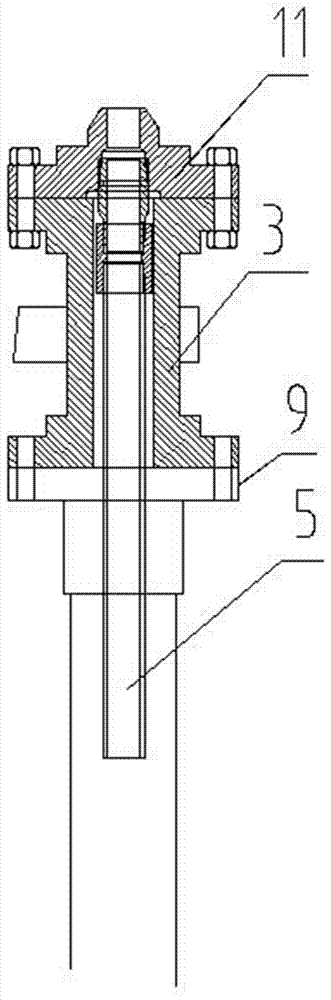
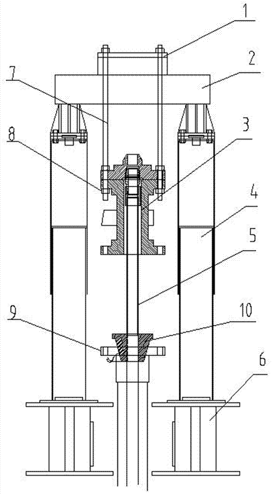
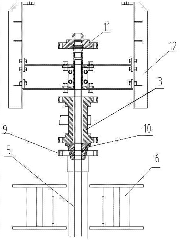
[0059] The invention proposes a hydraulic lifting device for replacing pipe strings and wellhead parts. Through the cooperation of the lifting system, the connecting mechanism and the pipe string locking device, the replacement of the wellhead can be completed without removing the entire pipe string in the well. , the time-consuming for replacement is only within 25% of the prior art. Greatly improve work efficiency, such as Figure 2-Figure 6 As shown, the following arrangement structure is adopted in particular: a lifting system and a connecting mechanism are provided, and the lifting system is connected with the wellhead device 3 to be replaced through the connecting mechanism; A string locking device 10 for locking the column 5.

[0060] When in use, when the existing wellhead (such as figure 1 When replacing the wellhead device 3 to be replaced as shown), the lifting system is arranged above the existing wellhead, and the lifting system is connected with the wellhead de...

Embodiment 2

[0062] This embodiment is further optimized on the basis of the above-mentioned embodiments, further to better realize the present invention, such as Figure 2-Figure 6 As shown, the following arrangement structure is adopted in particular: the lifting system includes a door-shaped lifting device and a pipe string lifting device 1, and the pipe string lifting device 1 is arranged on the top of the door-shaped lifting device; the door-shaped lifting device It includes two lifters 4, two support bases 6 and a lifting beam 2, and the two lifters 4 are respectively arranged on the two support bases 6, the lifting beam 2 is overlapped on the two lifters 4, and the pipe string is lifted The device 1 is arranged on the top of the lifting beam 2, and the pipe string lifting device 1 is connected with the wellhead device 3 to be replaced through a connecting mechanism.

[0063] When setting and using, a supporting base 6 is respectively set at a suitable position on both sides of the e...

Embodiment 3

[0065] This embodiment is further optimized on the basis of any of the above embodiments, further to better realize the present invention, such as Figure 2-Figure 6 As shown, the following arrangement structure is adopted in particular: the lifter 4 adopts a hydraulic lifter, and the lifter 4 is detachably arranged on the support base 6, and the lifting beam 2 is detachably arranged on the lifter 4. When setting, the lifting The lifter 4 adopts a hydraulic lifter, and the lifter 4 is detachably arranged on the support base 6, so as to facilitate the separation and adjustment of the lifter 4 and the support base 6, and also to facilitate the transfer; the support base 6 is preferably detachably arranged on the Replacement of the existing wellhead; the lifting beam 2 is also installed on the top of the two lifters 4 in a detachable manner, so that the lifter 4, the support seat 6 and the lifting beam 2 just form a gate-shaped structure, so that the effective While ensuring the ...


PUM


Abstract

The invention discloses a hydraulic hoisting device for replacing a pipe column and a wellhead part. The hydraulic hoisting device is provided with a hoisting system and a connecting mechanism, wherein the hoisting system is connected with a wellhead device to be replaced through the connecting mechanism; the hydraulic hoisting device further comprises a pipe column locking device which is mainly used for locking a downhole pipe column connected with the wellhead device; a method comprises the following steps: 1) mounting the hoisting system; 2) detaching the wellhead device; 3) assembling a wellhead four-way joint. By adopting the hydraulic hoisting device for replacing the pipe column and the wellhead part, wellhead replacement is carried out, and a pipe arrangement step is saved; the downhole pipe column only needs to be partially lifted, and then the downhole pipe column is locked by utilizing the matched pipe column locking device; then the whole weight of the downhole pipe column is transferred to an outer pipe, so that a wellhead can be replaced under the condition that the whole downhole pipe column is not detached, and furthermore, the working efficiency of wellhead maintenance work is effectively improved, and the maintenance time is reduced; the time consumption in a replacement process is only no more than 25 percent that of the prior art.

Description

technical field [0001] The invention relates to the field of workover operation technology and the like, in particular to a hydraulic lifting device and method for replacing pipe strings and wellhead components. Background technique [0002] Oil and gas extraction is the process of extracting oil and natural gas buried in underground oil layers from the ground. The way oil and gas are extracted from the ground to the surface can be divided into self-injection and artificial lift according to whether artificial energy needs to be added to the wellbore fluid. Artificial lift oil recovery includes: gas lift oil recovery, pumping unit rod pump oil recovery, submersible electric centrifugal pump oil recovery, hydraulic piston pump oil recovery and jet pump oil recovery, etc. [0003] In the process of oil and natural gas extraction, workover operation is an important link. Oil wells, gas wells and water wells may fail at any time during self-spraying, oil pumping, water injecti...

Claims


Application Information

Patent Timeline
Patent Type & Authority Applications(China)
IPC IPC(8): E21B23/04
CPCE21B23/04
Inventor 梅宗禄
Owner 梅宗禄
Why Eureka
Try Eureka