Eureka AIR delivers breakthrough ideas for toughest innovation challenges, trusted by R&D personnel around the world.

Piston engine system and control method thereof

A technology of piston engine and turbocharger, applied in the direction of internal combustion piston engine, combustion engine, machine/engine, etc., can solve the problem of increased power consumption of the impeller in the latter stage and the inability to guarantee the output of the latter two stages of turbines, so as to reduce the power consumption. power, increase power output, and reduce fuel consumption

Inactive Publication Date: 2017-07-11
INST OF ENGINEERING THERMOPHYSICS - CHINESE ACAD OF SCI
View PDF6 Cites 4 Cited by
  • Summary
  • Abstract
  • Description
  • Claims
  • Application Information

AI Technical Summary

Problems solved by technology

With the use of multi-stage turbocharging, the intake air is compressed by the front impeller, and the temperature of the rear gas rises. When the pressure ratio and flow rate are the same, the temperature is proportional to the power consumption of the impeller, which greatly increases the power consumption of the rear impeller.
At the same time, after the exhaust gas drives the first-stage turbine to do work, the temperature will drop rapidly, and the lack of air cannot guarantee the work of the second-stage turbine. In addition, for the power system that works at a wide altitude range from the ground to 20,000m, How to ensure the high-efficiency operation of turbocharging at different altitudes has brought challenges to the application of piston engine systems to high-altitude and long-endurance aircraft.

Method used


Image

  • Piston engine system and control method thereof
  • Piston engine system and control method thereof

Examples


Embodiment Construction

[0032] In order to make the objectives, technical solutions and advantages of the present invention clearer, the present invention will be described in further detail below with reference to the accompanying drawings and embodiments.

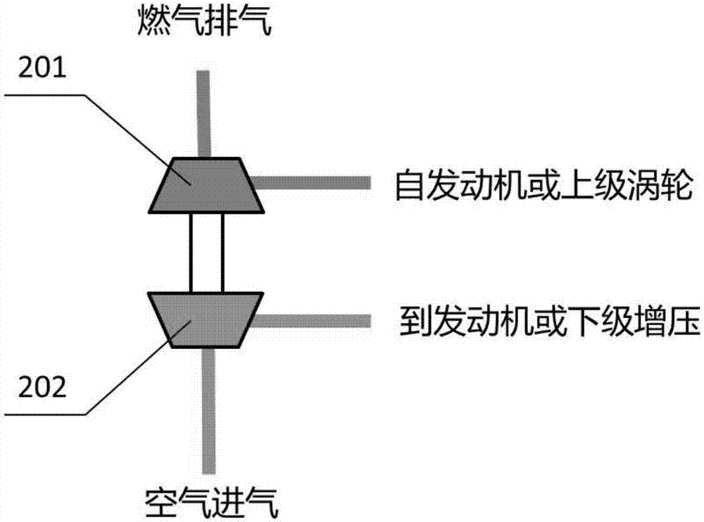
[0033] like figure 1 As shown, the single-stage turbocharger used in the present invention is composed of a centrifugal impeller 202 and a centripetal turbine 201 coaxially in a back-to-back manner. The air is axially intake and radially exhausted, and enters the piston engine or the lower stage supercharger; the gas is radially intaked and axially exhausted, and the gas comes from the piston engine after combustion or after passing through the upper stage turbine.

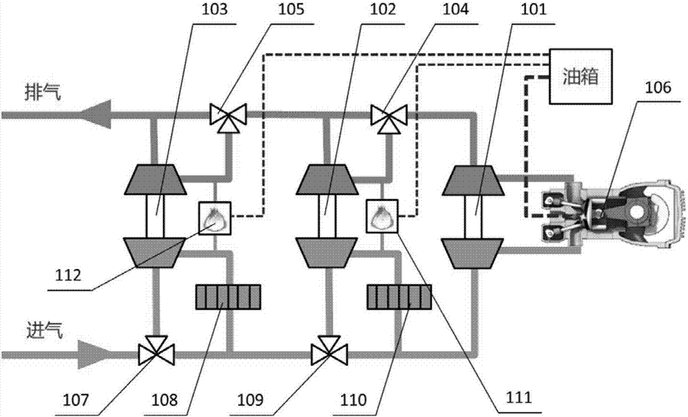
[0034] like figure 2As shown, the piston engine system of the present invention applied to a high-altitude long-endurance aircraft includes a grade I turbocharger 101, a grade II turbocharger 102, a grade III turbocharger 103, and a grade II gas three-way valve 104. , Class III g...


PUM


Abstract

The invention discloses a piston engine system which is applied to an aircraft during high-altitude long flight. The piston engine system comprises a piston engine (106), triple turbochargers (101, 102 and 103), corresponding fuel gas three-way valves (104 and 105), corresponding air three-way valves (107 and 109), inter-stage coolers (108 and 110), inter-stage after-burning devices (111 and 112) as well as matched air, fuel gas and fuel oil pipelines. According to the piston engine system disclosed by the invention, air and fuel gas three-way valves are controlled, so that the stage number of a turbocharging device accessed into the system is controlled, and the piston engine system is guaranteed to normally work under different gas inlet states from ground to a 20000m high altitude. Meanwhile, the intercoolers are additionally arranged turbocharging stages and after-burning devices are additionally arranged among turbine stages, so that consumed work of downstream supercharging is reduced, output work of a downstream turbine is increased, normal work of a multi-stage turbocharging system is guaranteed, and a fuel consumption rate is reduced by improving efficiency.

Description

technical field [0001] The invention relates to a piston engine system, in particular to a piston engine system applied to a high-altitude long-endurance aircraft and a control method thereof. Background technique [0002] The present invention relates to the development of piston engine systems derived from high-altitude unmanned aerial vehicles. With the vigorous development of UAV technology, various types of UAVs with different functions and performances continue to emerge. Power unit is one of the key technologies of UAV, which directly affects the performance, cost and reliability of UAV. For specific high-altitude long-endurance aircraft (the ceiling is greater than 20,000m and the endurance is greater than 2h), it is required to have the characteristics of long endurance, low fuel consumption, long life, large load and high reliability, and the power system generally adopts turbofan engine or piston engine. , while the piston engine has the characteristics of low f...

Claims


Application Information

Patent Timeline
Patent Type & Authority Applications(China)
IPC IPC(8): F02B37/013F02B37/12
CPCF02B37/013F02B37/12Y02T10/12
Inventor 肖波曹文宇谭春青董学智赵洪雷刘锡阳
Owner INST OF ENGINEERING THERMOPHYSICS - CHINESE ACAD OF SCI
Why Eureka
Eureka Blog
Learn More