Thin film leveling guide roller mechanism

A guide roller mechanism and flattening technology, applied in the field of film flattening guide roller mechanism, can solve the problems of inability to completely solve the problem of wrinkling and shrinkage, reduce the film cooling shrinkage rate, and cannot remove wrinkles and flatten the film, and achieve ideal wrinkle and flattening effects. Smooth sliding and anti-slip effect

Inactive Publication Date: 2017-07-14
浙江班萘特复合材料股份有限公司
View PDF1 Cites 6 Cited by
  • Summary
  • Abstract
  • Description
  • Claims
  • Application Information

AI Technical Summary

Problems solved by technology

[0004] However, this invention can only cool down the rollers to eliminate the temperature difference, reduce the cooling shrinkage rate of the film, and alleviate the wrinkling phenomenon of the film, but cannot completely solve the problem of wrinkling and shrinkage, and cannot achieve wrinkle removal and smoothing of the film that has already wrinkled and shrunk.

Method used


Image

  • Thin film leveling guide roller mechanism
  • Thin film leveling guide roller mechanism
  • Thin film leveling guide roller mechanism

Examples


Embodiment 1

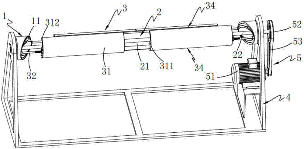
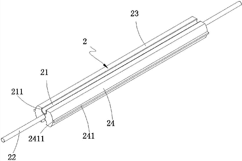
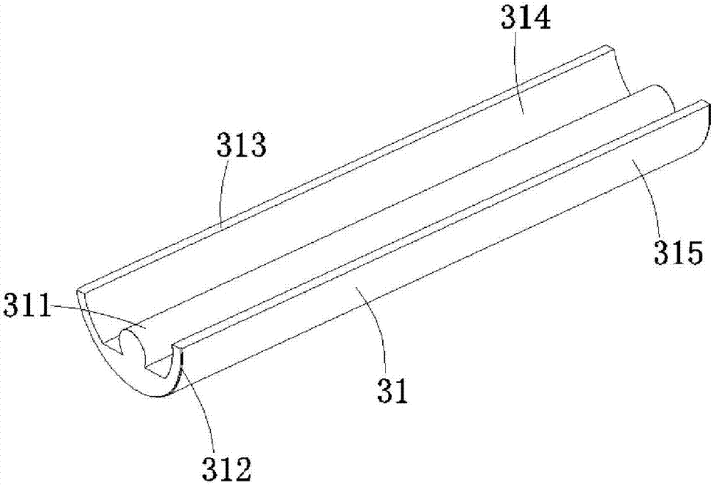
[0035] Such as figure 1 As shown, a film leveling guide roller mechanism includes a limit mechanism 1 horizontally symmetrically installed on both sides of the cloth roller frame 4, a guide roller 2, a leveling mechanism 3, a cloth roller frame 4 and a driving device 5, and the guide roller 2 The two ends of the two ends are respectively rotatably mounted on the corresponding limit mechanism 1, and one end passes through the corresponding limit mechanism 1 and is fixedly connected with the drive device 5; the leveling mechanism 3 includes rollers 2 along the guide rail A leveling assembly 33 arranged symmetrically in the radial direction, the leveling assembly 33 all includes a leveling unit 34 arranged symmetrically along the axial direction of the guide roller 2, the leveling unit 34 includes a leveling slider 31 and a push-pull mechanism 32, one end of the push-pull mechanism 32 is connected to the The leveling slider 31 is fixedly connected, and its other end is slidably c...

Embodiment 2

[0043] figure 1 , Figure 4 , Figure 5 , Figure 6 , Figure 7 and Figure 8 It is a structural schematic diagram of a film leveling guide roller mechanism involved in the second embodiment; figure 1 As shown, the parts that are the same as or corresponding to those in Embodiment 1 use the reference numerals corresponding to Embodiment 1. For the sake of simplicity, only the differences from Embodiment 1 will be described below. The difference between this embodiment two and embodiment one is:

[0044] Such as Figure 4 and Figure 5 As shown, the limiting mechanism 1 includes a semi-closed annular groove body 11, and the central axis of the limiting mechanism 1 is provided with a through hole 12;

[0045] Further, the inner surface of the semi-closed annular groove body 11 is an inclined surface, and an annular limiting guide rail groove 110 is provided on the inner surface, and the first limiting part 117 and the second limiting guide groove 110 are provided on the ...


PUM


Abstract

The invention relates to the field of film processing, and specifically discloses a film leveling guide roller mechanism, including a limit mechanism, a guide roller, a leveling mechanism and a driving mechanism. The limit mechanism is coaxially arranged at both ends of the guide roller and fixed on a On the roller frame, there is a limit guide rail groove inside which limits the activity of the leveling mechanism; the leveling mechanism is arranged on the outside of the guide roller; the outer circumferential surface of the guide roller is symmetrically provided with guide rail grooves; the leveling mechanism includes a leveling A slider and a push-pull mechanism, the push-pull mechanism is arranged at one end of the leveling slider; the leveling slider is provided with a guide rail, and through the sliding fit of the guide rail and the guide rail groove, the relative alignment of the leveling mechanism on the surface of the guide rail roller is realized. Sliding, and the leveling mechanism rotates synchronously with the guide roller, and the push-pull mechanism slides relative to the circumference in the limit guide groove, driving the leveling slider to reciprocate sliding on the guide roller, so as to realize the expansion and wrinkle removal of the film.

Description

technical field [0001] The invention relates to the field of film processing, in particular to a film leveling guide roller mechanism. Background technique [0002] PE film and polyethylene film are usually used for sheet coating, and PE film and polyethylene film are usually produced continuously at high temperature. The temperature drop process will occur during the forming process of the film, and the surface temperature will drop during the film transmission process A certain amount of shrinkage will cause the film to be uneven and wrinkled, which will affect the production quality and production efficiency of the film. Therefore, it is necessary to expand the film in time to remove wrinkles. [0003] Application No. 201420611551.7 discloses a film cooling roller, which includes a roller and a cooling pipe. There are discharge holes at both ends of the roller. The roller is rotatably connected to the cooling pipe. A spiral flow channel is formed between the cooling pipe...

Claims


Application Information

Patent Timeline
Patent Type & Authority Applications(China)
IPC IPC(8): B29C53/18
CPCB29C53/18
Inventor 金庭峰
Owner 浙江班萘特复合材料股份有限公司
Why Eureka
Try Eureka