Super magnetic levitation track traffic system

A rail transit and maglev technology, applied in the field of rail transit system, can solve the problems of high construction cost and maintenance cost, and achieve the effect of fast construction speed and reduced construction cost

Inactive Publication Date: 2017-07-14
天津信云风科技有限公司
View PDF5 Cites 0 Cited by
  • Summary
  • Abstract
  • Description
  • Claims
  • Application Information

AI Technical Summary

Problems solved by technology

Until today, magnetic levitation technology has been invented, but the main problem is that the cost of construction and maintenance is too high

Method used


Image

  • Super magnetic levitation track traffic system
  • Super magnetic levitation track traffic system
  • Super magnetic levitation track traffic system

Examples


Embodiment Construction

[0014] The specific embodiments of the present invention will be further described below in conjunction with the accompanying drawings. It should be noted here that the descriptions of these embodiments are used to help understand the present invention, but are not intended to limit the present invention. In addition, the technical features involved in the various embodiments of the present invention described below may be combined with each other as long as they do not constitute a conflict with each other.

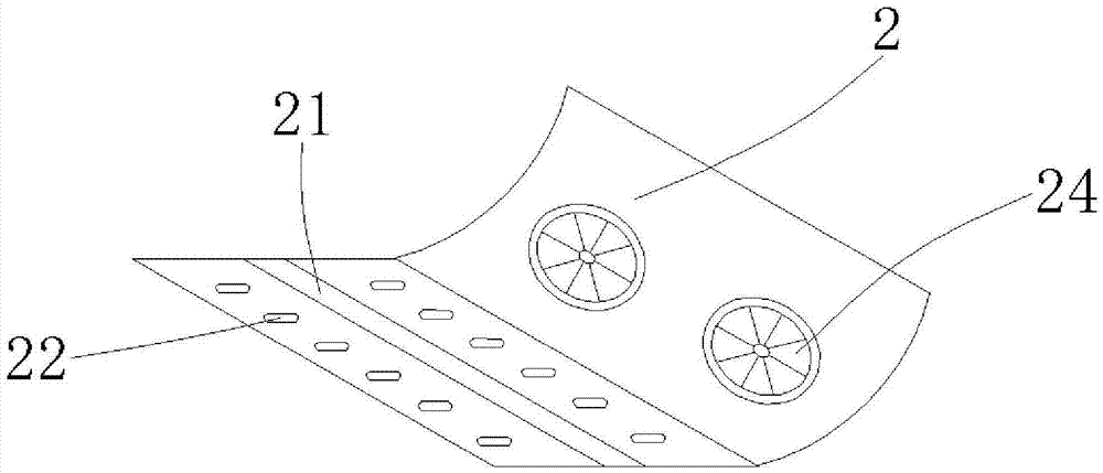
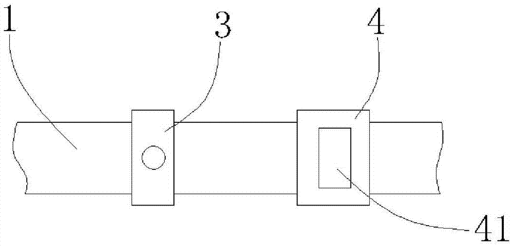
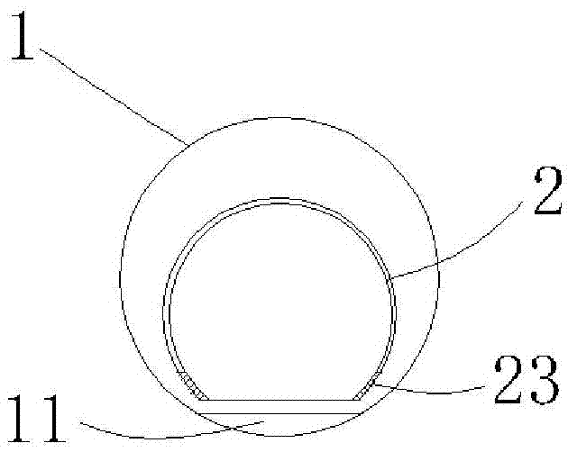
[0015] Such as figure 1 and figure 2 As shown, a super maglev rail transit system includes a track 1, a compartment 2, a life station 3 and an isolation shutter 4. The track 1 is a barrel-shaped track with a diameter of 3m and a hollow structure 11 is arranged on the track 1. On the track 1, a carriage 2 is arranged every 36m. The carriage 2 is cylindrical and has a flat bottom surface. Superconducting coils 23 are arranged on the two waists of the carriage 2. The car...


PUM


Abstract

The invention provides a super maglev rail transit system, which includes a rail, a carriage, a life station and an isolation shutter. In the present invention, the stator is on the car body, and the rotor is on the road, so that the construction cost is greatly reduced, and the construction cost is half of that of the high-speed rail, and the construction speed is fast, no noise, no pollution, energy saving, and is not affected by the climate .

Description

technical field [0001] The invention relates to a rail transit system, in particular to a super magnetic levitation rail transit system. Background technique [0002] Since the history of free orbit, fast running has been one of the dreams of human beings. Through unremitting efforts, including the enlargement of locomotives, the introduction of electrification, and the improvement of vehicle running performance, the running speed of the railway has indeed been improved. However, relying on the support and drive of the wheels, and the guidance of the vehicle on the rail and the cross-sectional shape of the vehicle, limit the running speed of the railway. Since the middle of the 19th century, after the invention of jets, hovercraft and other means of transportation, countries have been prompted to develop floating railways, which have surpassed the limits of railways and achieved high-speed travel. Until today, maglev technology has been invented, but the main problem is th...

Claims


Application Information

Patent Timeline
Patent Type & Authority Applications(China)
IPC IPC(8): B61B13/08
CPCB61B13/08
Inventor 张喜明
Owner 天津信云风科技有限公司
Why Eureka
Try Eureka