Pressure transducer and preparation method thereof

A pressure sensor and circuit board technology, applied in the direction of measuring fluid pressure, piezoelectric devices/electrostrictive devices, piezoelectric/electrostrictive/magnetostrictive devices, etc., can solve product sealing and long-term stability of overload capacity Corrosion resistance and other problems, to achieve the effect of improving long-term product stability, reducing stress, and improving sealing

Inactive Publication Date: 2017-07-14
芜湖恒铭电子科技有限公司
View PDF9 Cites 8 Cited by
  • Summary
  • Abstract
  • Description
  • Claims
  • Application Information

AI Technical Summary

Problems solved by technology

[0003] In the process of realizing the present invention, the inventors found that the prior art has at least the following problems: leading to relatively large problems in the sealing performance, overload capacity, long-term stability and corrosion resistance of the product

Method used


Image

  • Pressure transducer and preparation method thereof
  • Pressure transducer and preparation method thereof
  • Pressure transducer and preparation method thereof

Examples


Embodiment 1

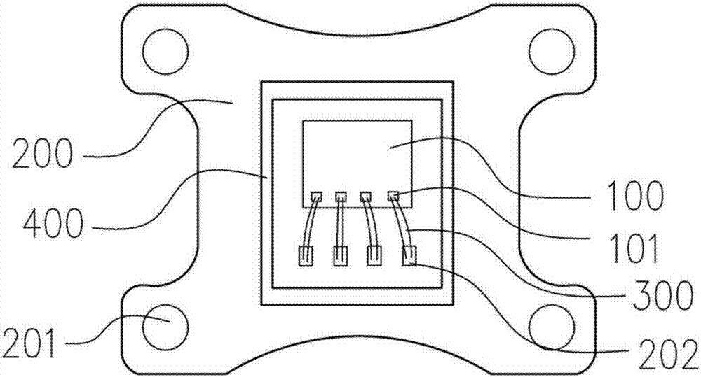
[0035] see Figure 1-3 , a pressure sensor having:

[0036] A circuit board 202, the side of the circuit board is provided with an inwardly recessed arc edge, and the circuit board is also provided with a circuit board pad 202 and a positioning hole 201;

[0037] The chip 100 is installed on the lower part of the circuit board, and the chip and the circuit board are bound by double gold wires; and the chip covering glue 700 is set to cover the chip;

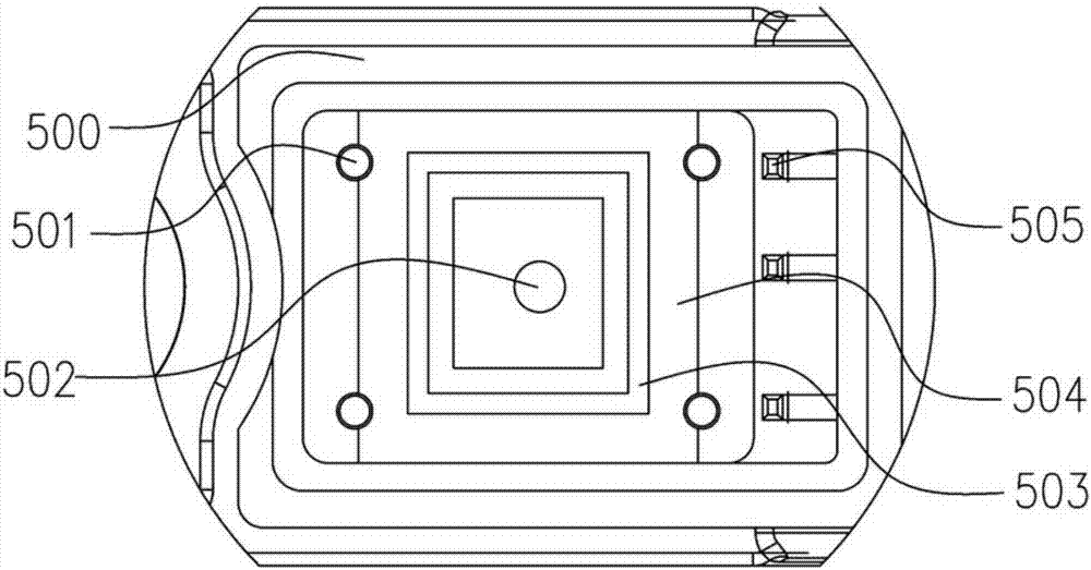
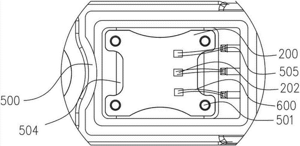
[0038] The housing 500, the housing 500 is provided with a first installation groove, the bottom of the first installation groove is provided with a second installation groove, the chip is installed in the second installation groove, and the bottom of the second installation groove is provided with a vent hole 502; The circuit board is installed in the first installation groove; steps 503 are provided around the notch of the second installation groove, and the steps 503 support the circuit board; grooves 504 are arranged on the ...

Embodiment 2

[0047] The manufacturing method of sensor, concrete implementation is as follows

[0048] 1. Chip packaging on the circuit board

[0049] Bond the MEMS chip ML808 to the circuit board through a die bonder, and fix it with a high-temperature curing adhesive. Use a 1.0mil gold wire to connect the pads of the MEMS chip and the pads 202 of the circuit board through a fully automatic bonding machine. Perform double-wire bonding, and the binding single-wire tensile force requires more than 7g. After the bonding is completed, use a manipulator to bond and fix the plastic retaining ring 400 around the periphery of the MEMS chip, and seal the chip covering glue 700 in the retaining ring 400 .

[0050] The bonding of the chip adopts 1.0mil double gold wire bonding, the gold wire has good conductivity and ductility, and the double gold wire bonding reduces the risk of the bonding wire disconnection, which improves the fatigue life of the product and the durability of the product. servic...


PUM


Abstract

The invention discloses a pressure transducer and a preparation method thereof. The pressure transducer comprises a circuit board, a chip, a shell and a gel. The side of the circuit board is provided with an inward concave curved sides and a circuit board bonding pad and a location hole. The chip is arranged on the lower part of the circuit board. The shell is provided with a first mounting groove, and the chip is arranged in a second mounting groove which is arranged in the bottom of the first mounting groove. An air hole is arranged in the bottom of the second mounting groove. The circuit board is arranged in the first mounting groove; steps are arranged around the notch of the second mounting groove; a groove is arranged on the periphery of the steps and is filled with silica gel. A registration mast is adapted with the location hole of the circuit board. A contact pin bonding pad is arranged at the shell. The contact pin bonding pad is bonded with the circuit board through aluminium wire bonding wire. The first mounting groove is filled with the gel. The transducer has the advantages of good anti-corrosive properties, good long term stability and high overload capability.

Description

technical field [0001] The invention belongs to the technical field of pressure sensors, in particular to a pressure sensor and a manufacturing method thereof. Background technique [0002] In the existing method of manufacturing gas pressure sensors for vehicles, the chip package generally adopts a single-wire bonding structure, the circuit board and the housing are welded by wires or flexible boards, and the whole machine is generally assembled by epoxy resin glue or silica gel potting or sealing The structure of ring pressing is completed; [0003] In the process of realizing the present invention, the inventors found that the prior art has at least the following problems: leading to relatively large problems in the sealing performance, overload capacity, long-term stability and corrosion resistance of the product. Contents of the invention [0004] The technical problem to be solved by the present invention is to provide a pressure sensor with good corrosion resistanc...

Claims


Application Information

Patent Timeline
Patent Type & Authority Applications(China)
IPC IPC(8): B81B3/00B81C1/00G01L11/00
CPCB81B3/0027B81B2201/0264B81C1/00134B81C1/00261B81C2201/00G01L11/00
Inventor 李玲玲朱宗昌李志斌
Owner 芜湖恒铭电子科技有限公司
Why Eureka
Try Eureka