A thermal fatigue test device

A test device, thermal fatigue technology, applied in measurement devices, greenhouse gas reduction, instruments, etc., can solve the problems of uneven sample injection, cumbersome experimental operation, different cooling rates, etc., to improve reliability and uniform injection angle. Effect

Active Publication Date: 2022-07-12
SHANGHAI JIAOTONG UNIV +1
View PDF6 Cites 0 Cited by
  • Summary
  • Abstract
  • Description
  • Claims
  • Application Information

AI Technical Summary

Problems solved by technology

However, the thermal fatigue test device in Patent Document 1 must first be evacuated and then filled with protective gas before the thermal fatigue test can be performed. In the case of repeated sampling and observation, the experimental operation is cumbersome
In addition, the thermal fatigue test device of Patent Document 1 adopts a top-spray air cooling with a single nozzle, which may easily cause uneven air injection and different cooling speeds at different positions of the sample.

Method used


Image

  • A thermal fatigue test device
  • A thermal fatigue test device
  • A thermal fatigue test device

Examples


Embodiment 1

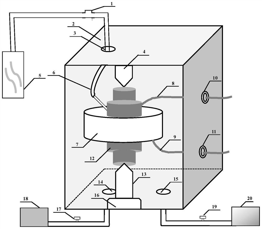
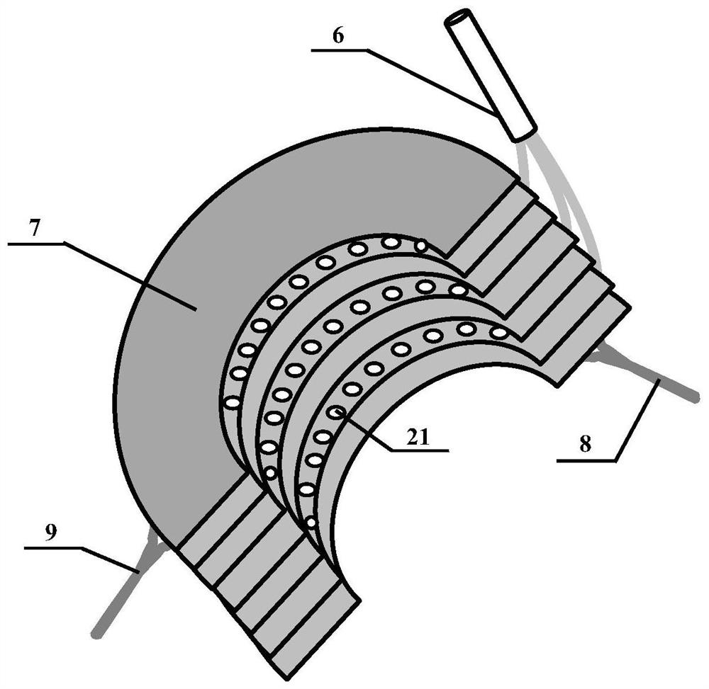
[0028] In the case where the number of tests is small and the experimental samples need to be removed for observation every few heating cycles, in order to facilitate repeated sampling operations, the vacuum cover can be directly sprayed on the sample through the ventilation coil to achieve the The oxidation protection of the sample avoids the trouble of repeated vacuuming. The specific process is as follows. The commonly used aluminum alloy die-casting mold steel SKD 61 is used as the test sample. The upper and lower thimbles are used to fix the test sample in the heating coil. By adjusting the positions of the upper and lower thimbles, the test sample is placed in the center of the heating coil. Open the air inlet valve, spray protective gas (nitrogen or argon) through the air inlet of the gas cooling part, and maintain the low-pressure air injection state to create a local protective gas atmosphere around the test sample inside the heating coil. Then, the heating coil was ...

Embodiment 2

[0030] When the number of tests is large and repeated sampling is not required for observation, it is recommended to use a vacuum hood to protect the samples from oxidation. The specific process is as follows: take SKD 61 steel for aluminum alloy die-casting molds as the test sample, use the upper thimble and the lower thimble to fix the test sample in the heating coil, and adjust the position of the upper thimble and the lower thimble to place the test sample on the heating coil. Right in the center. Close the intake valve and exhaust valve, open the exhaust valve and vacuum system, evacuate the vacuum cover to a vacuum state, close the exhaust valve and vacuum system. Open the air inlet valve, fill the protective gas (nitrogen or argon) through the air inlet of the gas cooling part until the pressure in the vacuum hood reaches 1 atmosphere, then open the exhaust valve, and energize the heating coil, and heat for 5s to make The temperature of the test sample was raised to 65...


PUM


Abstract

The invention discloses a thermal fatigue test device, which is characterized by comprising a heating part, which is composed of a heating coil spirally formed into a cylindrical shape, and is used for heating a test sample; a gas cooling part, which has a length of the cylindrical shape. The heating coils are alternately distributed in the direction, and the air outlets are evenly distributed on the inner side; and a sample fixing part is used for fixing the test sample in a way that the test sample passes through the heating coil and the inside of the gas cooling part the test sample. The thermal fatigue test device of the present invention is a thermal fatigue test device with simple operation and uniform cooling of the sample, which can obtain a thermal fatigue surface with no pollution and no oxidation on the surface, which is convenient for subsequent characterization and testing (especially the characterization of residual stress), and improves thermal performance. Reliability of thermal fatigue performance evaluation of materials such as die steel.

Description

technical field [0001] The invention relates to a thermal fatigue test device, in particular to a thermal fatigue test device of hot work die steel. Background technique [0002] The main feature of the working conditions of hot work die steel is the intermittent contact with the hot metal, and the surface must be cooled with water, oil, air and other media after contact. Therefore, its working state is repeated heating and cooling, the surface structure undergoes repeated thermal expansion and cold contraction, and repeatedly undergoes tensile and compressive stress, and eventually surface cracks appear, that is, thermal fatigue failure occurs. [0003] Thermal fatigue test is an important means to predict the thermal fatigue life of die steel. Accurately characterizing thermal fatigue cracks and evaluating the evolution law of thermal fatigue stress are the prerequisites for accurate prediction. At present, domestic and foreign researchers have reported many reports on th...

Claims


Application Information

Patent Timeline
Patent Type & Authority Patents(China)
IPC IPC(8): G01N3/60
CPCG01N3/60G01N2203/0057G01N2203/0062G01N2203/0073G01N2203/0224Y02E30/30
Inventor 王博赵幸锋顾剑锋
Owner SHANGHAI JIAOTONG UNIV
Why Eureka
Try Eureka