Gas solenoid rotor engine power device

A rotary engine and power plant technology, applied in the direction of engine components, machines/engines, combined engines, etc., can solve the problems of expensive construction, pressure difference, large fuel consumption, etc., and achieve the effect of improving efficiency

Inactive Publication Date: 2017-07-14
罗显平
View PDF2 Cites 4 Cited by
  • Summary
  • Abstract
  • Description
  • Claims
  • Application Information

AI Technical Summary

Problems solved by technology

The biggest disadvantage of nuclear power: expensive construction, expensive follow-up maintenance, and tens of hundreds of millions to hundreds of billions of dollars
[0010] 1. The gas turbines in the prior art basically use the coaxial structure of the axial flow compressor and the turbine to work, and 1 / 2 to 2 / 3 of the output power of the turbine is consumed by the compressor
[0011] 2. When the exhaust steam discharged from the steam turbine is cooled into water by the cooling water of the condenser, its volume can suddenly drop to about 1 / 10,000 of the original volume, causing a high degree of vacuum in the condenser and at the outlet of the steam turbine, which can cause a very high degree of vacuum. Large pressure difference, which pushes the turbine to output more mechanical work, while the gas turbine cannot do this
[0012] 3. The working temperature of gas turbine is usually higher than 1000℃, while modern supercritical steam is only 600℃ high temperature, which is doomed to high cost and maintenance cost of gas turbine and shorter life than steam turbine, hindering the development of manufacturing high-power gas turbine
[0013] 4. The thermal efficiency of the gas turbine decreases rapidly under partial load, and the fuel consumption at no-load is large, while the steam turbine does not have this point
[0016] The high-power gas turbine engines in the prior art basically use the turbine coaxial synchronously driven speed compressor to work and output power externally, and the speed of rotation is lower than 3000 r / min, which requires high-speed rotation to generate large flow and high pressure. unfavorable for compressors

Method used


Image

  • Gas solenoid rotor engine power device
  • Gas solenoid rotor engine power device
  • Gas solenoid rotor engine power device

Examples


Embodiment Construction

[0056] Specific embodiments of the present invention will be further described below.

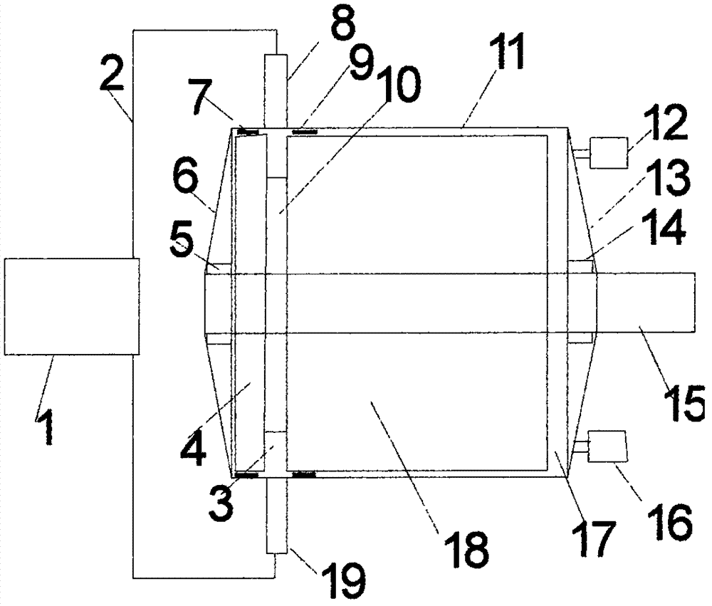
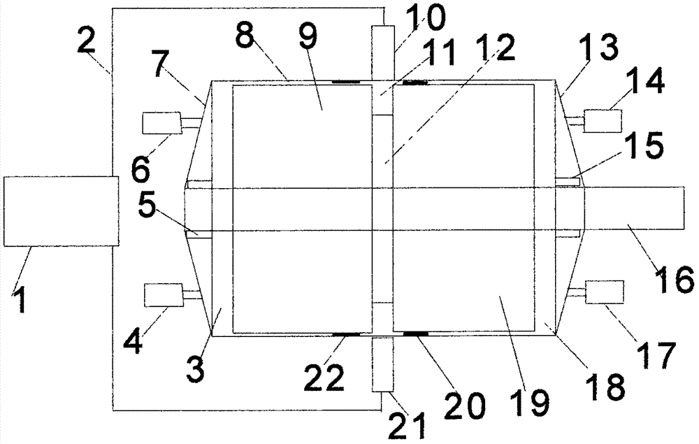
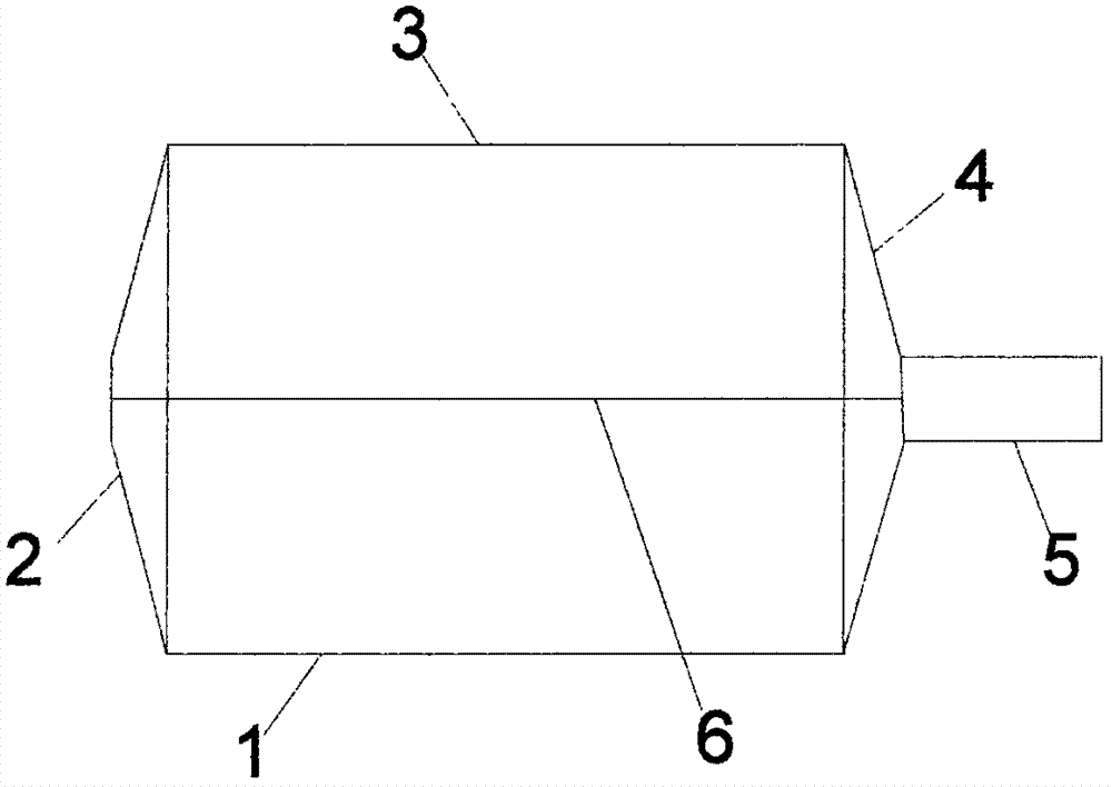
[0057] A gas helical rotor engine power device, including a gas turbine engine power device, is composed of a gas generator and a single or double-ended helical rotor engine. Make a head cylinder-neck cylinder-built-in coil cylinder on the body as a whole, or make a left built-in coil cylinder-neck cylinder-right built-in coil cylinder on the same cylinder As a whole, the cross-sectional area of ​​the spiral tube from the air inlet to the exhaust port is gradually released; the gas generator is composed of an air compressor output pipe connected to the combustion chamber of the flame tube, and the exhaust port of the combustion chamber of the flame tube is connected to the combustion chamber. The annular combustor of the helical rotor engine is air-connected, the compressed air output by the air compressor unit is heated by the flame cylinder combustor, and high-temperature and high-pressur...


PUM


Abstract

The invention discloses a power device. It is composed of a gas generator and a single or double-ended helical tube rotor engine. The cross-sectional area of ​​the coil tube from the inlet to the exhaust port is gradually released. The gas generator is composed of an air compressor output pipe and a flame tube combustion chamber. Composed of air connection, the exhaust port of the flame tube combustion chamber is connected with the annular combustion chamber of the helical rotor engine, the compressed air output by the compressor is heated by the flame tube combustion chamber, and high temperature and high pressure gas is generated in the annular combustion chamber of the helical rotor engine, single-ended Or the double-ended helical tube rotor continuously changes the flow direction of the gas flowing through the various helical tubes and enters the exhaust chamber to drive the helical tube rotor engine to output mechanical work. Make the circumferential speed of the rotor of the spiral rotary engine greater than 500 m / s, and the rotational speed can be higher or lower than 3000 rpm, and a gas spiral with higher power and more technical advantages than the existing technology can be produced Rotary engine power unit. It can be used as conventional power for ships and commercial power generation.

Description

technical field [0001] The invention relates to a turbine engine power device, in particular to a gas spiral tube rotor engine power device. Background technique [0002] The turbine engine power plant includes a gas turbine engine power plant and a steam turbine engine power plant, with high rotational speed and large working fluid flow. The gas turbine engine is small in size, light in weight, large in specific power, high in stand-alone power, and fast in starting. The weight and volume of the body per unit of power are smaller than those of internal combustion engines. Internal combustion engine, it is these and other factors that make it first applied in aviation. However, even if the latest single crystal blade is used as the core technology to increase the maximum gas temperature of the gas turbine engine to 1500°C, the thermal efficiency of the gas turbine engine in the prior art can only reach about 42%. The power of a single steam turbine engine can reach more th...

Claims


Application Information

Patent Timeline
Patent Type & Authority Applications(China)
IPC IPC(8): F01D1/38F01D25/14F01D17/00F01D25/12F01D13/00
CPCF01D1/38F01D13/00F01D17/00F01D25/125F01D25/145
Inventor 罗显平
Owner 罗显平
Why Eureka
Try Eureka