Fully automatic oil fume detection equipment

A testing equipment, fully automatic technology, applied in the direction of analyzing materials, instruments, etc., can solve the problems of manual operation, poor timeliness, high cost of human resources, avoid damage to the health of workers, optimize the detection accuracy, and shorten the sampling period.

Inactive Publication Date: 2017-07-14
SHENZHEN LEADNOVEL ENVIRONMENTAL PROTECTION ENG CO LTD
View PDF6 Cites 2 Cited by
  • Summary
  • Abstract
  • Description
  • Claims
  • Application Information

AI Technical Summary

Problems solved by technology

The standard oil fume monitoring report submission period is 15 working days, so it generally takes about 20 natural days from oil fume monitoring to submitting the oil fume monitoring report. One of the main reasons for the long submission period of the monitoring report is that the oil fume detection equipment is too outdated , which needs to be divided into two parts: on-site sampling and laboratory testing and analysis, all of which need to be manually operated by professionals
The existing oil fume detection methods are poor in timeliness and high in human resource costs. These two defects have been criticized by people in the industry and the tested objects.
At this stage, conventional oil fume detection uses an ordinary infrared spectrophotometer, which requires at least one hour of equipment warm-up time. At the same time, it needs to manually prepare a standard series and then manually complete the comparison test. The detection cycle is long and the accuracy is extremely low, which can only reach ±0.02 mg / m 3 measurement accuracy
The existing oil fume detection method will volatilize a large amount of carbon tetrachloride during the detection process, which will directly cause adverse effects on the health of operators, and carbon tetrachloride can only be used once, and waste carbon tetrachloride also poses a threat to the environment

Method used


Image

  • Fully automatic oil fume detection equipment
  • Fully automatic oil fume detection equipment
  • Fully automatic oil fume detection equipment

Examples


Embodiment 1

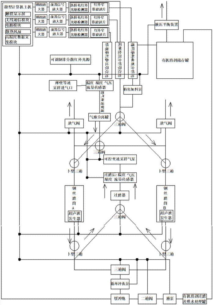
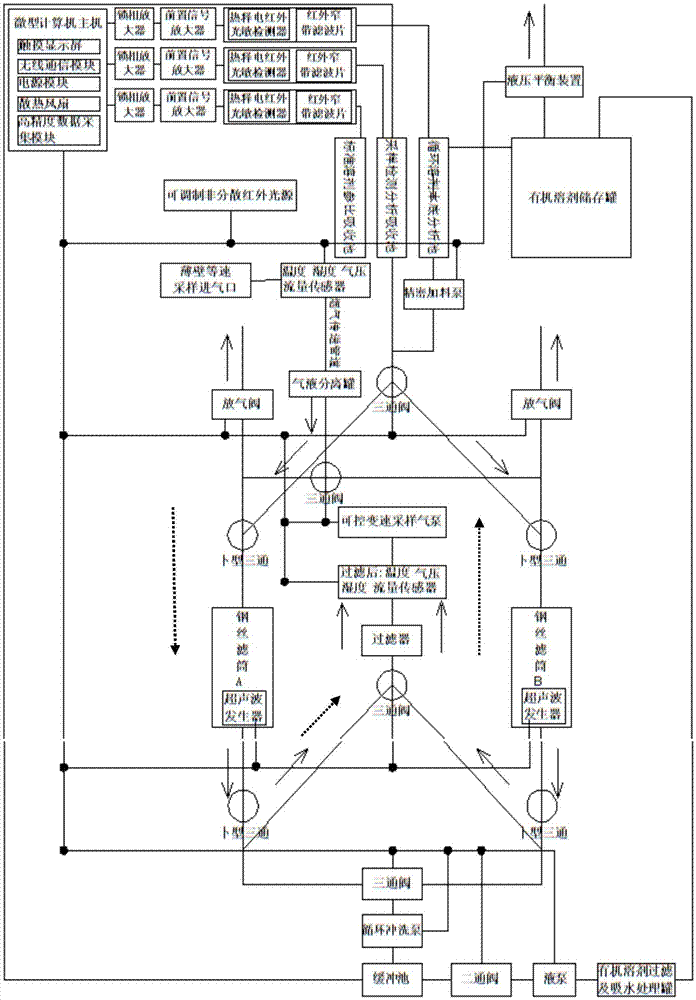
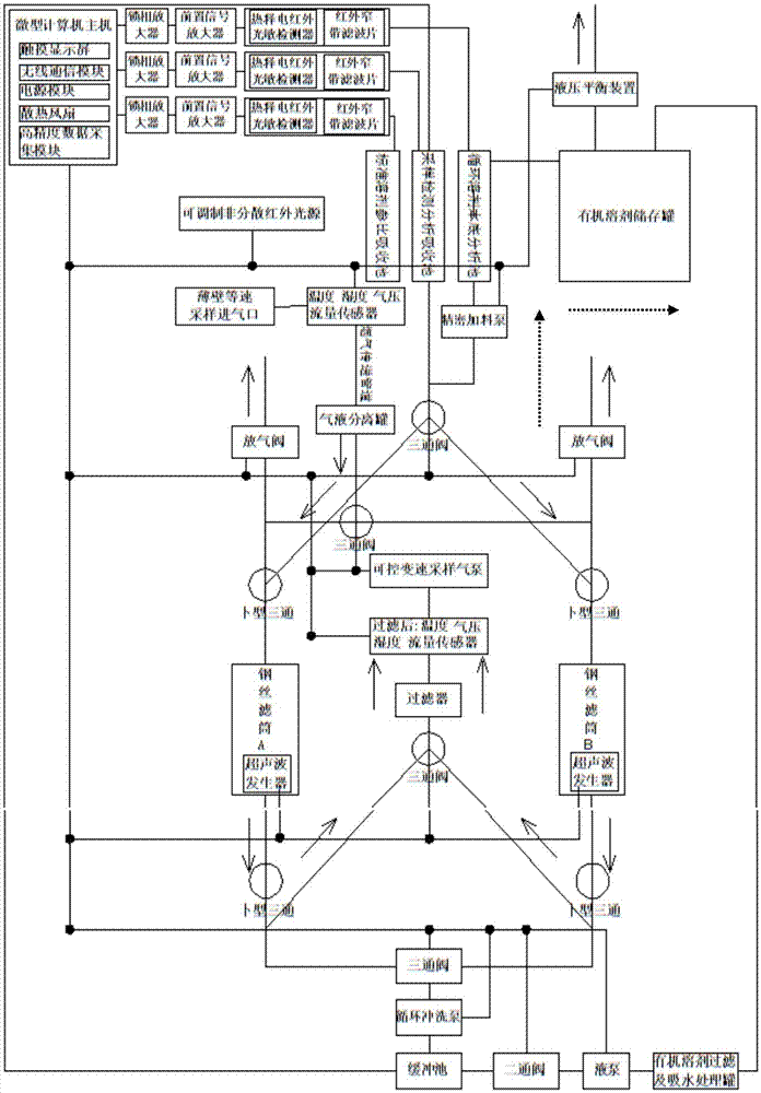
[0031] see Figure 1-Figure 8, the present invention provides a technical solution: a fully automatic oil fume detection device, including three parts: an isokinetic sampling gun, a flue gas conveying pipe, and a detection equipment body; After entering the detection equipment body, it is filtered through the steel wire filter cartridge and then discharged from the equipment. After the sampling period is over, the microcomputer host automatically controls the completion of solvent injection, ultrasonic cleaning of the steel wire filter cartridge, infrared spectroscopic absorption method detection, multi-parameter conversion correction and other procedures, and finally outputs oil fume concentration detection. result. A thin-wall constant velocity sampling inlet and flue gas physical parameter sensors such as flue gas velocity, flue temperature, flue gas humidity, and flue gas pressure are arranged at the head of the constant velocity sampling gun, and the flue gas transmission...


PUM

PropertyMeasurementUnit
lengthaaaaaaaaaa
diameteraaaaaaaaaa

Abstract

The present invention discloses fully automatic oil fume detection equipment, and relates to the technical field of oil fume detection equipment, wherein the fully automatic oil fume detection equipment comprises a constant velocity sampling gun, a flue gas conveying pipeline, and a detection equipment body. According to the present invention, oil fume sample gas sampled by the constant velocity sampling gun enters the detection equipment body through the flue gas conveying pipeline; the oil fume sample gas is filtered by a steel wire filtration cylinder; the filtered gas is discharged out of the equipment; after the sampling period is ended, a micro-computer automatically controls to complete solvent injection, ultrasonic wave flushing of the steel wire filtration cylinder, infrared spectrophotometry detection, multi-parameter conversion correction and other procedures; finally the oil fume concentration detection result is output.

Description

technical field [0001] The invention relates to the technical field of oil fume detection equipment, in particular to a fully automatic oil fume detection equipment. Background technique [0002] As we all know, my country promulgated GB18483-2001 "Catering Fume Emission Standard" in 2001, the standard appendix A "Catering Fume Sampling Method and Analysis Method" stipulates the metal filter cartridge absorption and infrared spectrophotometry to determine the sampling and analysis of cooking fume The method is a statutory standard oil fume detection method. Appendix B "Technical Specifications for Oil Fume Sampler" stipulates the technical indicators of the steel wire filter cartridge for collecting oil fume. Humidity, air pressure, on-site manual sampling, on-site manual replacement of sampling heads, manual ultrasonic cleaning of steel wire filter cartridges in the laboratory, manual calibration, manual detection, manual calculation and correction, etc., are all manually com...

Claims


Application Information

Patent Timeline
Patent Type & Authority Applications(China)
IPC IPC(8): G01N35/00
CPCG01N35/00
Inventor 戴飞鸿许楷楠刘欣伍晓光张义祥余生镇赖佩佩张家双詹伟忠黄期辉俞献东
Owner SHENZHEN LEADNOVEL ENVIRONMENTAL PROTECTION ENG CO LTD
Why Eureka
Try Eureka