

Generator preferably of wind turbine
A technology for wind turbines and generators, applied in wind engines, engines, wind power generation, etc., can solve problems such as increased power loss and increased heat production, and achieve the effects of reducing torque fluctuations, reducing hot spots, and high cooling performance
- Summary
- Abstract
- Description
- Claims
- Application Information
AI Technical Summary
Problems solved by technology
Method used
Image

Examples
Embodiment Construction
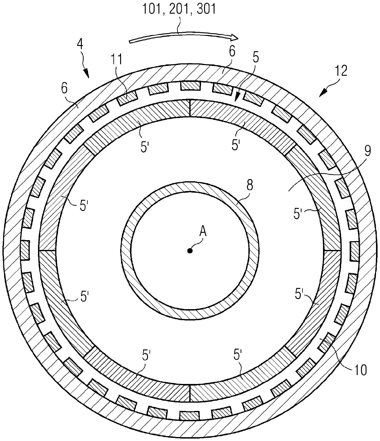
[0069] figure 1 A schematic partial sectional view of a wind turbine 1 is shown. The wind turbine 1 is a direct drive wind turbine intended for onshore or offshore applications and comprises a rotatable rotor hub 2 having a number of rotor blades 3 attached to the rotor hub 2 . The rotor hub 2 is adapted to transmit a rotational movement to a rotor 4 . The rotor 4 is rotatably supported with respect to the stator 5 , and includes permanent magnets 11 mounted on the inner surface of the rotor 4 and facing the stator 5 . Thus, the rotor 6 is supported on a corresponding bearing unit 7 arranged on a non-rotatable hollow shaft 8 , whereby the stator 5 is supported on a stator frame 9 . The stator frame 9 is supported directly on a central hollow shaft 8 which extends along a 90° rounded angle and is connected to a vertical wind turbine tower 20 .
[0070] The air gap 10 extends in the axial direction 404 between the stator 5 and the permanent magnets of the rotor 4 . The radia...
PUM
| Property | Measurement | Unit |
|---|---|---|
| Thickness | aaaaa | aaaaa |
Abstract
Description
Claims
Application Information