Light stimulus device

A light stimulation, electrical contact technology, applied in the field of optogenetics, can solve the problems of the inability to adjust the distance between two LED needles, the reduction of battery life, and the low fiber coupling efficiency, achieving low power, reduced loss, and long service life. Effect

Active Publication Date: 2017-07-18
HANGZHOU NUOWEI MEDICAL TECH CO LTD
View PDF3 Cites 5 Cited by
  • Summary
  • Abstract
  • Description
  • Claims
  • Application Information

AI Technical Summary

Problems solved by technology

[0006] 1. The light emitted by the LED lamp stimulates the brain of the animal through the optical fiber, and the coupling efficiency of the optical fiber is too low;
[0007] 2. The distance between the two LED pins cannot be adjusted;
[0008] 3. Due to the long distance between the LED light and the stimulation position, the intensity of the light reaching the stimulation position is reduced; therefore, a higher-power LED light is required. In this way, for the battery with the same power, the high-power LED light will consume more power. Resulting in reduced battery life, unable to meet user needs

Method used


Image

  • Light stimulus device
  • Light stimulus device
  • Light stimulus device

Examples


Embodiment Construction

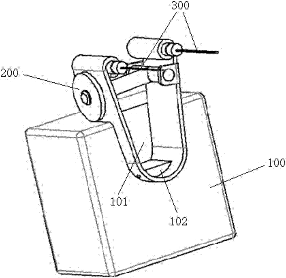
[0056] Such as Figure 1-9 The light stimulation device shown mainly includes a receiver 100 , a fixing frame 200 and double-sided LED stimulation needles 300 .

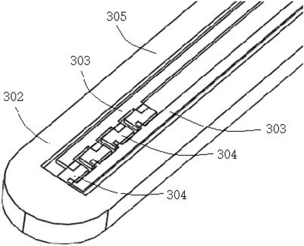
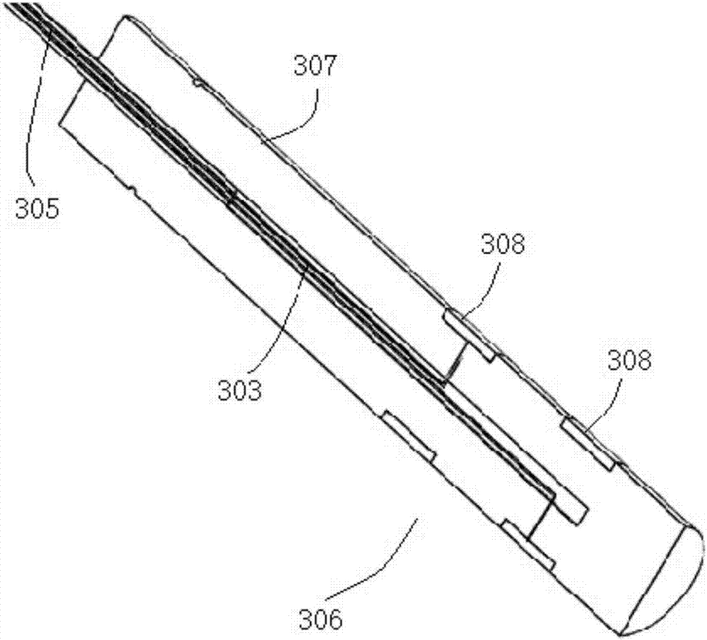
[0057] Such as figure 2 and image 3 In the structure of the LED stimulating needles shown, each LED stimulating needle 300 includes an optical fiber part, one end of the optical fiber 305 is a stimulating end 302 , and the other end is an electrical connection end 306 .

[0058] At the stimulating end 302 , an LED lamp 304 for photostimulation is installed, and the LED lamp 304 is directly arranged at the tip of the optical fiber 305 . In this embodiment, the optical fiber part is divided into five layers. The first part is a layer of thicker PET material, which has a supporting function. The second layer is a temperature sensor. The third layer is a layer of thinner PET material. The first layer is 4 LED lights, and the top layer is PET material. Please refer to the existing literature: 1.Fabrication and appli...


PUM


Abstract

The invention discloses a light stimulus device. The light stimulus device comprises two stimulation needles, and two ends of each stimulation needle are respectively a stimulation end and an electric connection end. The stimulation ends are provided with LED used for the light stimulus, and the electric connection ends are provided with electric connection contacts, which are electrically connected, and are used to supply the LED with power. A fixing rack is provided, and has two fixing parts, a spacing between which is adjustable. The electric connection ends of the two stimulation needles are disposed on corresponding fixing parts, and each fixing part is provided with a power supply contact, which is cooperated with the corresponding electric connection contact to form the electric connection. By adopting the implantable type optogenetics double-side LED stimulation needles, the spacing between the two LED stimulation needles can be adjusted at will according to different positions of target nucleuses of a simulated object head part, and therefore loss of light in an optical fiber caused by a distance is reduced. By adopting the small power LED lamp, service lifetime is prolonged, and optical coupling efficiency is improved.

Description

technical field [0001] The invention relates to the field of optogenetic technology, in particular to a light stimulation device with adjustable spacing LED needles on both sides. Background technique [0002] In the wired optogenetic system, the fiber optic connector ceramic ferrule is also called the ceramic ferrule body. A precision-centered cylinder in a fiber optic connector plug with a microhole in the center to hold the fiber in place. It is a high-precision special ceramic element made of nano-zirconia (ZrO2) material through a series of formulations and processing. The error of its aperture and true roundness is 0.5 mm. The manufactured connector is a detachable and classified optical fiber active connector, which makes the connection and conversion scheduling of the optical channel more flexible and can be used for debugging and maintenance of the optical communication system. [0003] The development momentum in the field of optical communication technology is s...

Claims


Application Information

Patent Timeline
Patent Type & Authority Applications(China)
IPC IPC(8): A61N5/06
CPCA61N5/0601A61N2005/0612A61N2005/0626A61N2005/063A61N2005/0651
Inventor 王鹤张文涛方元
Owner HANGZHOU NUOWEI MEDICAL TECH CO LTD
Why Eureka
Try Eureka