Magnetic sealing guide rail system and powder laying system suitable for powder sintering equipment

A technology of sintering equipment and guide rail system, applied in the field of 3D printing, can solve the problems affecting the accuracy of parts, high surface finish, low coil spring life, etc., and achieve the effect of overcoming motion defects, good application prospects, and smooth transmission.

Pending Publication Date: 2017-07-18
WUHAN POLYTECHNIC
View PDF8 Cites 5 Cited by
  • Summary
  • Abstract
  • Description
  • Claims
  • Application Information

AI Technical Summary

Problems solved by technology

The other end of the powder spreading device is suspended in the air. The biggest disadvantage of this cantilever structure powder spreading device is that the fixed end slightly shakes, resulting in a large vibration at the suspended end, which affects the smoothness of the powder spreading surface and thus affects the accuracy of the workpiece.
And because the working environment of the powder sintering equipment is harsh, the entire use process is in a dust environment with a diameter of 60 microns to 100 microns, so it is necessary to isolate the working chamber from the guide rail. The components used in the prior art are steel belts driven by coil springs. However, the life of the coil spring is relatively low, so the entire part of the steel belt needs to be replaced for a period of time, and the replacement is more troublesome, resulting in inconvenience in use and an increase in cost. In order to solve this problem, this structure needs to be improved
[0003] At present, some researchers are also researching the issue of sealing to realize the automatic sealing of the track, such as patent 201610329058.X, but this kind of tr

Method used


Image

  • Magnetic sealing guide rail system and powder laying system suitable for powder sintering equipment
  • Magnetic sealing guide rail system and powder laying system suitable for powder sintering equipment
  • Magnetic sealing guide rail system and powder laying system suitable for powder sintering equipment

Examples


Embodiment 1

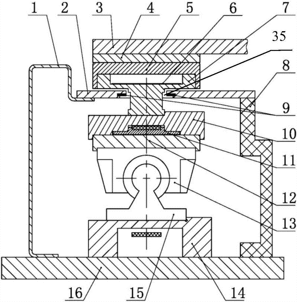
[0040] like Figure 1~Figure 5 As shown, a magnetic seal rail system suitable for powder sintering equipment, which is connected to the rail 15, includes side protection plates 1 and inner protection plates 8 on both sides of the rail 15, and a magnet-inlaid aluminum cover on the top of the rail 15. 2. T-shaped guide bridge 7, guide rail cover 5, sliding assembly, and transmission assembly. A groove body 35 is opened in the middle of the magnetic-inlaid aluminum cover plate 2, and permanent magnets 9 are arranged on both sides of the groove body 35. The groove body 35 of the magnetic aluminum cover plate 2 is covered with a stainless iron sheet 6 with a width greater than its groove width, and the length of the stainless iron sheet 6 is greater than that of the groove body 35 of the magnetic aluminum cover plate 2. Length; one end of the stainless iron sheet 6 is fixed on the front end or the rear end of the magnetic aluminum cover plate 2 with an iron sheet briquetting block ...

Embodiment 2

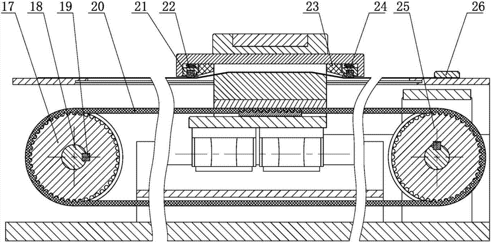
[0056] On the basis of Example 1, such as Figure 6 As shown, the pulley support assembly 25 includes two supports 27, a top cover 32, a synchronous pulley 31, a wheel shaft 29 with two ends smaller than the middle, and a bearing 30; the top cover 32 covers the two supports 27 Above, the synchronous pulley 31 is located between the two supports 27; the axle 29 is provided with a keyway, and the axle 29 is connected with the synchronous pulley 31 through the key 33 arranged in the keyway, so as to rotate together; The two ends of the axle 29 are respectively connected with the two supports 27 through bearings 30 .

[0057] like Figure 6 As shown, the support 27 is provided with a wheel shaft 29 mounting holes, and the outer side of the wheel shaft 29 mounting holes is provided with an end cover 28; the two ends of the wheel shaft 29 are fixedly connected with the inner ring side of the bearing 30, and the bearing 30 The side of the inner ring of the bearing 30 fits with the ...

Embodiment 3

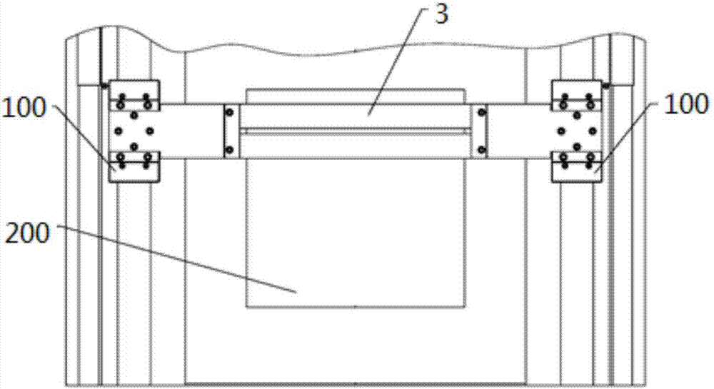
[0060] A powder spreading system for powder sintering equipment, such as figure 1 and Figure 7 As shown, it includes rails 15 on both sides, a magnetic sealing rail system 100 on the rails 15, and a powder spreading device 3. The magnetic sealing rail system 100 adopts the magnetic Sealed guide rail system; both ends of the powder spreading device 3 are connected to the magnetic seal guide rail system 100 on both sides of the track, the equipment working cylinder 200 is located in the middle between the two sides of the track 15, and the powder spreading device 3 is located in the equipment working cylinder 200; the magnetic seal guide rail system 100 moves on the track 15, driving the powder spreading device 3 to reciprocate above the equipment working cylinder 200.


PUM


Abstract

The invention discloses a magnetic sealing guide rail system and a powder laying system suitable for powder sintering equipment. The magnetic sealing guide rail system comprises a rail, a lateral protection plate, an inner protection plate, a cover plate located above the rail, a T-shaped guide bridge, a guide rail cover, a sliding assembly and a transmission assembly, wherein the lateral protection plate and the inner protection plate are located on the two sides of the rail. The middle of the cover plate is provided with a slot body, the two sides of the slot body are provided with permanent magnets, a cavity is formed among the lateral protection plate, the inner protection plate, the cover plate, the guide bridge and an iron magnetic component, and the transmission assembly, the sliding assembly and the rail are located in the cavity; and the transmission assembly is connected with the sliding assembly, drives the sliding assembly to move back and forth along the rail in the cavity and drives the inclined face of the guide bridge to pry the iron magnetic component up and move back and forth along the slot body. According to the magnetic sealing guide rail system and the powder laying system suitable for the powder sintering equipment, through the structure of the guide rail system in combination with the absorption function of the permanent magnets on iron materials, quite good sealing performance is achieved, and the magnetic sealing guide rail system and the powder laying system are compact and stable in structure, simple and reliable and low in cost.

Description

technical field [0001] The invention belongs to the technical field of 3D printing, and in particular relates to a magnetic seal rail system and a powder spreading system suitable for powder sintering equipment. Background technique [0002] In the powder sintering equipment used in 3D printing, the powder spreading action is realized by the driving mechanism driving the powder spreading device to move back and forth on the guide rails. The commonly used structure is that one end of the powder spreading device is fixed on two parallel guide rails, and the driving mechanism (generally It is the motor) to drive the timing belt, and the timing belt is fixed with the powder spreading device. When the motor rotates, it drives the powder spreading device to move back and forth on the guide rail, so as to realize the function of powder spreading. The other end of the powder spreading device is suspended in the air. The biggest disadvantage of this cantilever structure powder spread...

Claims


Application Information

Patent Timeline
IPC IPC(8): B29C64/153B29C64/205B29C64/20B33Y30/00
CPCB33Y30/00
Inventor 余立华朱红业冬
Owner WUHAN POLYTECHNIC
Why Eureka
Try Eureka