Plate loading machine

A feeder and plate technology, applied in the field of plate feeder, can solve the problems of low feeding efficiency, complex feeder structure, high cost, etc., and achieve the effect of improving feeding efficiency, fast feeding speed and improving efficiency

Active Publication Date: 2017-07-21
山东同利玻纤制品有限公司
View PDF8 Cites 8 Cited by
  • Summary
  • Abstract
  • Description
  • Claims
  • Application Information

AI Technical Summary

Problems solved by technology

[0002] The board feeding machine is used in conjunction with the board processing equipment. The traditional board feeding machine often sends out more than two boards at a time, which affects the board processing
The invention patent application with the application number 201610172297.9 discloses an automatic plate feeding machine, which can prevent more than two plates from entering the next processing equipment at the same time by setting a hinged baffle plate and a proximity switch at the discharge port However, there are the following disadvantages: (1) Since the channel steel is set above the supporting plate, and the channel steel is equipped with a pushing mechanism, it can only be loaded from the side of the frame body by a forklift, so it cannot be hoisted by driving, etc. The equipment is loaded from the top, while the side loading has the problem that the loading position is not easy to control, which leads to the skewed placement of the plates in the equipment. In addition, in order to save space above the ground and facilitate operation, it is often necessary to bury a part of the equipment. Under the ground, at this time, the material can only be loaded from the top, and the automatic sheet material loading machine is obviously impossible to realize. In addition, when the pallet cannot be stopped due to the failure of the power mechanism and other reasons, the pallet will crush the pushing mechanism; ( 2) The paddle needs to be pushed out of the platform every time before it can be returned to its original position. The stroke of the paddle is long and the feeding efficiency is low; (3) The patent application does not disclose how the height of the pallet rises each time However, if the rise of the pallet is too high, the paddle will push two or more plates at the same time. When two or more plates are sent out at the same time, the equipment will stop. Although it can prevent the wrong quantity of materials from being loaded, the shutdown will affect the efficiency of the entire production line; (4) The automatic plate loading machine has complex structure, high cost and high noise

Method used


Image

  • Plate loading machine
  • Plate loading machine
  • Plate loading machine

Examples


Embodiment Construction

[0021] In order to clearly illustrate the technical features of this solution, the specific implementation of the present invention will be further described below according to the accompanying drawings.

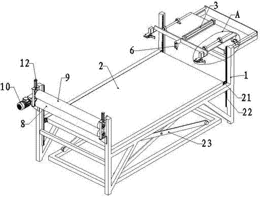
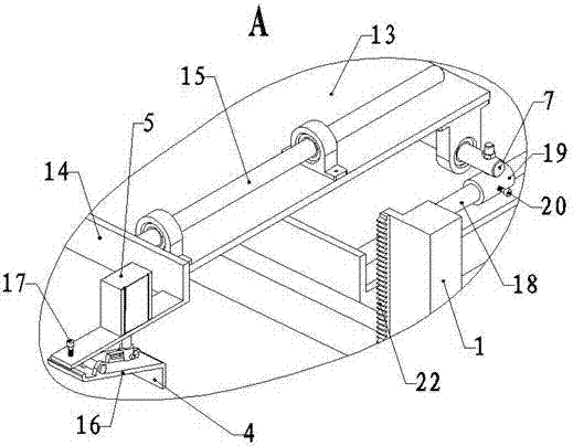
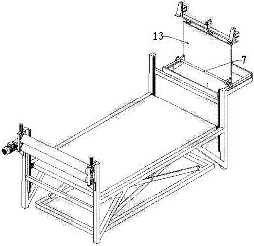
[0022] like Figure 1~Figure 5 As shown, a plate loading machine includes a frame body 1, a pallet 2, a scissor lift 23, a pushing mechanism and a pulling mechanism.

[0023] The supporting plate 2 is located inside the frame body 1 and is connected with the scissor lift 23. The four corners of the supporting plate 2 are provided with synchronous gears 21, and the frame body 1 is provided with a synchronous rack 22 meshing with the synchronous gear 21. Through the synchronous gear 21 and The synchronous rack 22 can improve the stability of the lifting of the scissor lift 23 and prevent the supporting plate 2 from being uneven and affecting the operation of the equipment.

[0024] The pushing mechanism is located at the head end of the frame body 1, and the pushing mechanism...


PUM


Abstract

The invention relates to the technical field of plate machining equipment, in particular to a plate loading machine. The plate loading machine comprises a frame body, a support plate, a lifting mechanism, a pushing mechanism and a pulling mechanism; the support plate is arranged in the frame body, and is connected with the lifting mechanism; the pushing mechanism is arranged at the head end of the frame body, and includes a pushing cylinder, a poking piece, a poking piece lifting cylinder and a limiting switch; the pushing cylinder is pivoted to the frame body through a horizontal shaft perpendicular to a loading direction, and can be kept in the horizontal direction; the poking piece lifting cylinder and the limiting switch are both connected with a piston rod of the pushing cylinder; the poking piece is connected with a piston rod of the poking piece lifting cylinder; the pulling mechanism is arranged at the tail end of the frame body; and the pulling mechanism includes a driving roller, a driven roller and a driving motor. The plate loading machine has such advantages as convenience to load materials, high efficiency, low cost and low noise.

Description

technical field [0001] The invention relates to the technical field of plate processing equipment, in particular to a plate feeder. Background technique [0002] The board feeding machine is used in conjunction with the board processing equipment. The traditional board feeding machine often sends out more than two boards at a time, which affects the board processing. The invention patent application with the application number 201610172297.9 discloses an automatic sheet material feeding machine, which can prevent more than two sheets from entering the next processing equipment at the same time by setting a hinged baffle plate and a proximity switch at the discharge port However, there are the following disadvantages: (1) Since the channel steel is set above the supporting plate, and the channel steel is equipped with a pushing mechanism, it can only be loaded from the side of the frame body by a forklift, so it cannot be hoisted by a crane The equipment is loaded from the t...

Claims


Application Information

Patent Timeline
Patent Type & Authority Applications(China)
IPC IPC(8): B65G59/02B65G47/06B65G47/82
CPCB65G47/06B65G47/82B65G59/026B65G2201/0282
Inventor 王侠
Owner 山东同利玻纤制品有限公司
Why Eureka
Try Eureka