
Mechanical tensile experiment testing device

A testing device and experiment technology, applied in measuring devices, using stable tension/pressure to test the strength of materials, scientific instruments, etc., can solve the problems of vulnerable and experimental personnel, lack of protection mechanism, low safety factor, etc., to achieve economical The effect of experiment time, improving safety factor and improving accuracy

Active Publication Date: 2017-07-21
RES INST OF PHYSICAL & CHEM ENG OF NUCLEAR IND
View PDF7 Cites 3 Cited by
  • Summary
  • Abstract
  • Description
  • Claims
  • Application Information

AI Technical Summary

Problems solved by technology

The Chinese patent with the notification number CN203519423U discloses "a mechanical tensile test device", which lacks a certain protection mechanism between the upper chuck and the lower chuck. Once the material under test breaks, or from the upper and lower chucks It is easy to injure the experimenters, and the safety factor is low. A mechanical tensile test device that can solve this problem still needs further research and development.

Method used


Image

  • Mechanical tensile experiment testing device
  • Mechanical tensile experiment testing device
  • Mechanical tensile experiment testing device

Examples


Embodiment 1

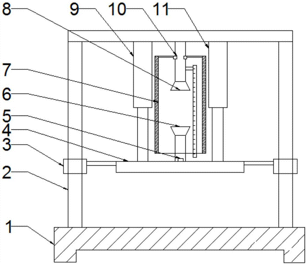
[0032] Such as figure 1 As shown, a kind of mechanical tensile experiment test device of the present invention comprises base 1, door-shaped frame 2, sliding collar 3, platform 4, load sensor 5, lower clamp 6, protective cylinder 7, upper clamp 8, the first Oil cylinder 9, second oil cylinder 11;

[0033] The top of the base 1 is fixed with a door-shaped frame 2, the column of the door-shaped frame 2 is provided with a sliding collar 3 slidingly connected with it, and the bottom end of the beam of the door-shaped frame 2 is fixedly provided with a first oil cylinder 9 and a second oil cylinder 11. , the first oil cylinder 9 and the second oil cylinder 11 are arranged vertically downward, and the left and right sides of the platform 4 are respectively fixedly arranged at the ends of the piston rods of the first oil cylinder 9 and the second oil cylinder 11;

[0034] The bottom end of the crossbeam of the portal frame 2 is fixedly provided with an upper clamp 8, the upper clamp...

Embodiment 2

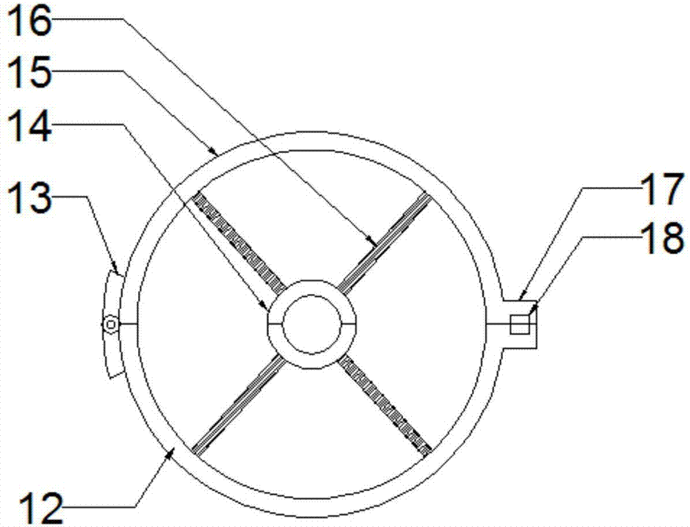
[0046] Such as figure 2 As shown, this embodiment is improved on the basis of Embodiment 1. The protective cylinder 7 includes a first half cylinder 12, a hinge 13, a locking half ring 14, a second half cylinder 15, a connecting frame 16, and a positioning protrusion. Edge 17;

[0047] One end of the first half cylinder 12 and the second half cylinder 15 is hinged together by a hinge 13, and the other end is a free end. The free ends of the first half cylinder 12 and the second half cylinder 15 are all provided with a positioning flange 17, The positioning flange 17 and the corresponding first half cylinder 12 or the second half cylinder 15 are in an integral structure, and the positioning flange 17 is provided with fixing parts, and the fixing parts fix the two positioning flanges 17 together, so that the first half The cylinder 12 and the second half cylinder 15 are fixed together;

[0048] The inner tops of the first half tube 12 and the second half tube 15 are provided ...

Embodiment 3

[0057] This embodiment is improved on the basis of embodiment 2, as image 3 as shown,

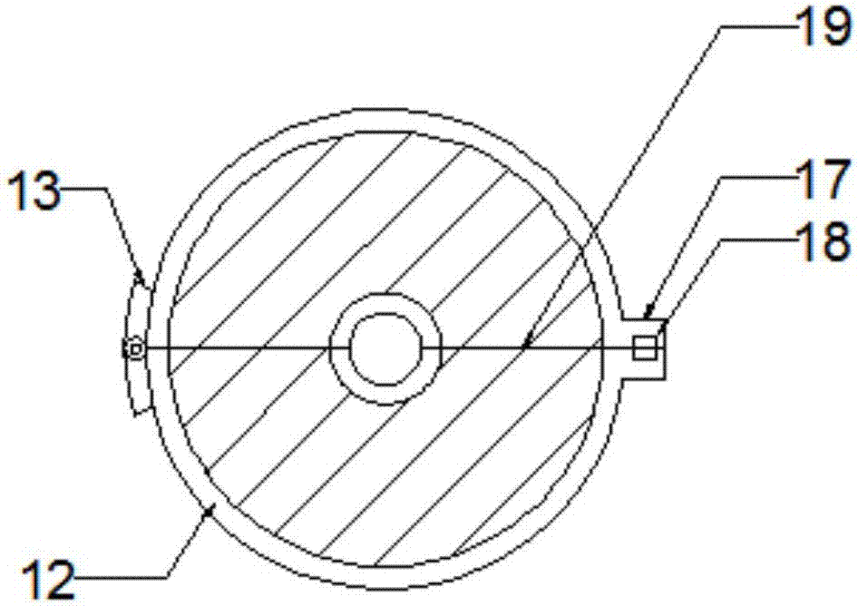
[0058] The tops of the first half cylinder 12 and the second half cylinder 15 are provided with a semicircular shield 19 , which is arranged between the cylinder walls of the first half cylinder 12 , the second half cylinder 15 and the locking half ring 14 .

[0059] 【Way of working】

[0060] The setting of the semicircular shield 19 can effectively prevent the material to be tested from popping up from the upper and lower ends of the protection tube 7 when it falls off or breaks, further improving the safety factor.


PUM


Abstract

The invention discloses a mechanical tensile experiment testing device. A door-shaped frame is fixedly arranged at the top end of a base; a sliding lantern ring which is in sliding connection with the door-shaped frame is arranged on a vertical column of the door-shaped frame; a first oil cylinder and a second oil cylinder are fixedly arranged at the bottom end of the transverse beam of the door-shaped frame; the first oil cylinder and the second oil cylinder are arranged downwards vertically; the top end of a platform is fixedly arranged at the tail ends of the piston rods of the first oil cylinder and the second oil cylinder; the left end and the right end of the platform are fixed on a left sliding lantern ring and a right sliding lantern ring through a bracket; an upper clamp is fixedly arranged at the bottom end of the transverse beam of the door-shaped frame; the upper clamp is arranged between the first oil cylinder and the second oil cylinder; a lower clamp is fixedly arranged at the top end of the platform; the upper clamp and the lower clamp are coaxially arranged up and down; a load sensor is arranged at the bottom of the lower clamp; a detachable protection cylinder is arranged on the upper clamp; the upper clamp and the lower clamp are covered inside the protection cylinder. The mechanical tensile experiment testing device has the beneficial effects of being high in testing precision and high in security coefficient.

Description

technical field [0001] The invention relates to the technical field of material performance testing, in particular to a testing device for mechanical tensile experiments. Background technique [0002] The mechanical properties of materials refer to the mechanical characteristics of materials when they are subjected to various external loads (tension, compression, bending, torsion, impact, alternating stress, etc.) under different environments (temperature, medium, humidity). The Chinese patent with the notification number CN203519423U discloses "a mechanical tensile test device", which lacks a certain protection mechanism between the upper chuck and the lower chuck. Once the material under test breaks, or from the upper and lower chucks It is easy to injure the experimenter, and the safety factor is low. A kind of mechanical tensile test device that can solve this problem still needs further research and development. Contents of the invention [0003] The object of the pr...

Claims


Application Information

Patent Timeline
Patent Type & Authority Applications(China)
IPC IPC(8): G01N3/02G01N3/10
CPCG01N3/02G01N3/10Y02E30/30
Inventor 张蓉
Owner RES INST OF PHYSICAL & CHEM ENG OF NUCLEAR IND
Learn More