
Self cleaning type airlock

An air lock and self-cleaning technology, applied in the field of air lock, can solve problems such as difficult feeding, long working time, increased air leakage rate, etc., and achieve the effect of overcoming complicated procedures, quick cleaning and short time-consuming

Inactive Publication Date: 2017-07-25
王丕新
View PDF5 Cites 2 Cited by
  • Summary
  • Abstract
  • Description
  • Claims
  • Application Information

AI Technical Summary

Problems solved by technology

During the operation of the air shutoff device, the impeller is easily entangled with debris such as ropes, ribbons, and packaging threads in the material. The increased wear and tear increases the rotational load of the impeller, making it difficult to unload the material, and even block and block the discharge channel. It will also increase the air leakage rate and seriously affect the dust removal ability of the cyclone dust collector
At present, the impeller cleaning operation can only be carried out manually, which has considerable safety hazards and long working hours, which affects the continuous operation of production

Method used


Image

  • Self cleaning type airlock
  • Self cleaning type airlock
  • Self cleaning type airlock

Examples


Embodiment Construction

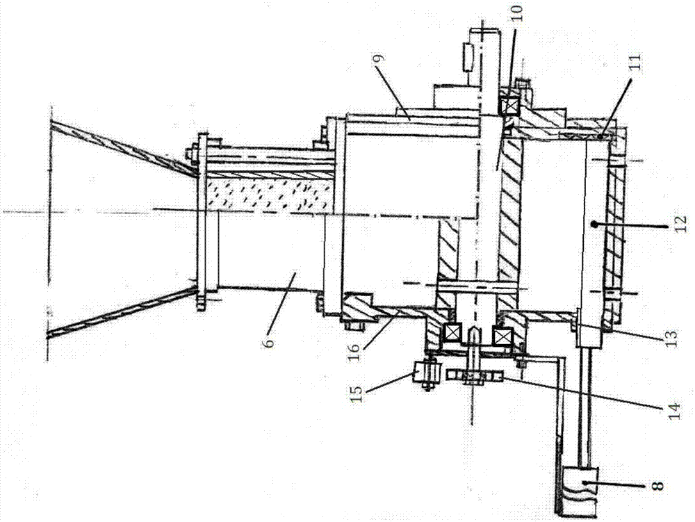
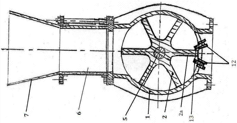
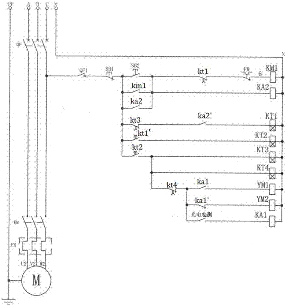
[0008] What is shown in the accompanying drawing is a specific structural structure of the self-cleaning air lock, which consists of an impeller casing 1, an impeller assembly, a control circuit and a cleaning knife assembly. The impeller 2 in the impeller assembly is fixed on the impeller shaft 5, and the impeller shaft 5 is rotatably supported between the two end covers 9, 16 and installed on the center line of the impeller casing 1. The upper opening of the impeller casing 1 passes through the barrel 6 and The discharge port of the unloader or the cyclone dust collector is connected, and the material is discharged from the discharge opening of the impeller casing 1 under the action of the impeller 2 .

[0009] The cleaning knife assembly in the air shutoff device includes a pneumatic cleaning knife 13, a slide rail 12, a buffer pad 11 and a blade detection part, such as figure 1 In the shown implementation structure, the slide rail 12 is composed of two parallel slats, and ...


PUM


Abstract

The application of the invention provides a self cleaning type airlock. The compositions of the self cleaning type airlock comprise an impeller machine shell, an impeller assembly, a control circuit and a cleaning knife assembly. The cleaning knife assembly comprises a pneumatic cleaning knife, a sliding rail, a buffering pad and a blade detecting part, the sliding rail is axially mounted at a discharging opening of the impeller machine shell, and the knife edge of the pneumatic cleaning knife radially extends into the circumference rotatably covered by an impeller; and the blade detecting part comprises an impeller synchronizing wheel mounted at the end cap external shaft end of an impeller shaft and a non-contacting sensor arranged on one side of the impeller synchronizing wheel. The cleaning knife assembly in the technical scheme can cut off and clean impurities entwined on the impeller within an extremely short time, and automatic control operation can be achieved.

Description

technical field [0001] What the application of the present invention relates to is an air lock. Background technique [0002] The air lock is widely used in the fields of rice milling, milling, grain and oil, grain, feed processing, chemical industry, medicine, tobacco, metallurgy, cement and dust removal. It is an important component equipment in the airflow conveying and ventilation and dust removal system. The air shutoff device is installed at the discharge port of the unloader or the cyclone dust collector. Its function mainly has two aspects: one is to ensure the smooth discharge of materials, and the other is to close the working air flow. Its structural composition includes the impeller casing and the impeller casing The impeller is rotated inside, and the upper opening of the impeller casing is connected to the discharge port of the unloader or cyclone dust collector through the flange. During the rotation of the impeller, the materials in the unloader or cyclone du...

Claims


Application Information

Patent Timeline
Patent Type & Authority Applications(China)
IPC IPC(8): B65G53/46
CPCB65G53/46
Inventor 王丕新
Owner 王丕新
Learn More