
Integrated millimeter wave tile type phased array antenna TR assembly

A phased array antenna, wave tile technology, applied in the antenna, antenna grounding switch structure connection, electrical components, etc., can solve the problems of size limitation, poor heat dissipation effect of functional layer, inability to complete circuit layout, etc., to achieve space utilization High efficiency and good versatility

Active Publication Date: 2017-07-25
10TH RES INST OF CETC
View PDF9 Cites 30 Cited by
  • Summary
  • Abstract
  • Description
  • Claims
  • Application Information

AI Technical Summary

Problems solved by technology

In addition, the chip at the bottom layer of this solution can obtain better heat dissipation (mW level) through metallized through-hole grounding, but the heat dissipation effect of the other several functional layers is very poor, and basically only some passive components can be mounted.
[0005] Chinese application number 201510890903.6 discloses a "millimeter-wave tile-type phased array antenna TR component" and proposes a tile-type TR component integration method based on a rib-like arrangement structure, which greatly improves the unit area utilization rate, but with the system The complexity of the application function increases. This solution is limited by the size of the TR component itself because all devices are located on the same horizontal layer; when the application function increases or the requirements are higher and the chip area needs to be expanded, the original architecture will not be able to complete the circuit layout.

Method used


Image

  • Integrated millimeter wave tile type phased array antenna TR assembly
  • Integrated millimeter wave tile type phased array antenna TR assembly
  • Integrated millimeter wave tile type phased array antenna TR assembly

Examples


Embodiment Construction

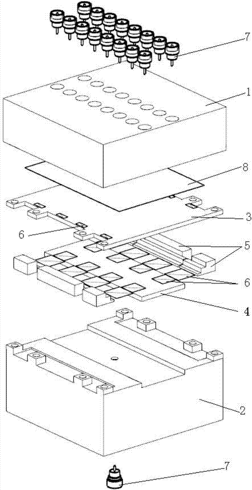
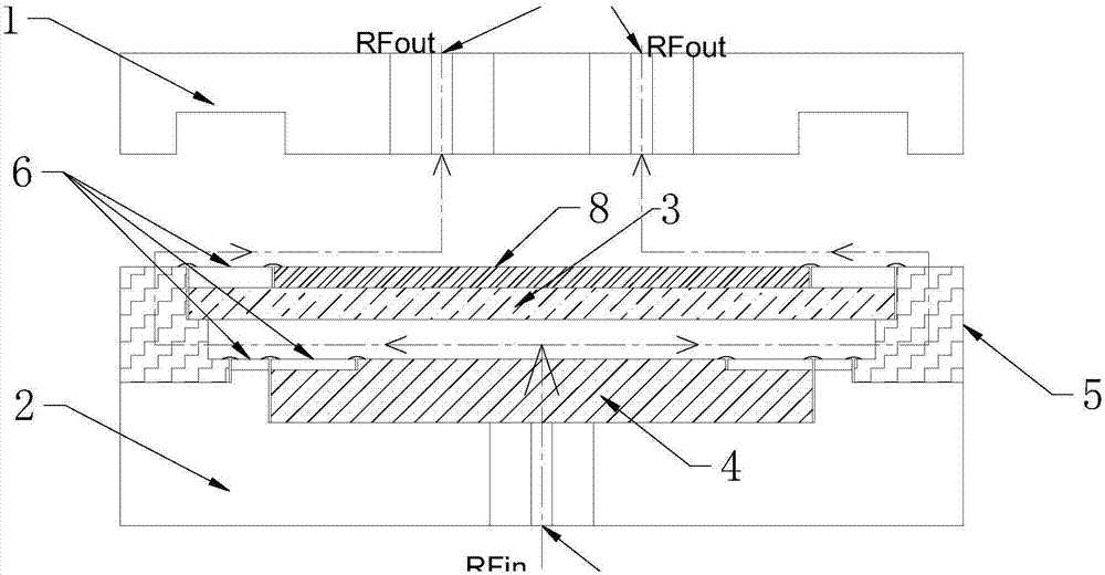
[0019] refer to figure 1 , figure 2 . In the embodiment described below, a millimeter-wave tile-type phased array antenna integrated TR assembly includes: an upper assembly 1 of the TR assembly integrated with at least two rows of linear array radio frequency ports, and a TR assembly with a common radio frequency port at the bottom Lower assembly 2. In the same TR component module, the TR component module is divided into two independent upper and lower expansion spaces from the built-in space in the Z direction, and between the TR component upper assembly 1 and the TR component lower assembly 2, from the top The circuit board 8, the middle metal separator 3, the second multilayer circuit board 5 and the first multilayer circuit board 4 are integrated sequentially from the bottom to form a multilayer circuit board assembly; on the multilayer circuit board assembly, the line array distribution There is a power chipset 6, and the first multilayer circuit board 4 is fixedly co...


PUM


Abstract

The invention provides an integrated millimeter wave tile type phased array antenna TR assembly and aims to realize a high integration level. The integrated millimeter wave tile type phased array antenna TR assembly is characterized in that an internal space of a TR assembly module in a Z direction is divided into upper and lower independent expansion spaces, a circuit board (8), a middle metal barrier (3) and a multi-layer circuit board assembly are sequentially integrated between an upper TR assembly assembling body and a lower TR assembly assembling body from up to down, the multi-layer circuit board assembly is distributed with chip sets (6) in a linear array mode, a first multi-layer circuit board is fixedly connected with a groove at a lower portion of a second multi-layer circuit board to form an integrated fixedly-connected assembly, the integrated fixedly-connected assembly is fixedly connected with rectangular bosses at two side edges of the lower assembling body, a large power device is integrated in the lower expansion space close to the lower assembling body, and electrical connection between the two independent expansion spaces is realized through the second multi-layer circuit board.

Description

technical field [0001] The invention relates to a two-dimensional active phased array antenna that can work in satellite communication, radar, guidance and other systems. Its working frequency band is the millimeter wave frequency band, and it supports a tile-type TR component with a single-channel transmission power of several watts. Background technique [0002] With the gradual expansion of the working frequency band to higher frequencies, the system working frequency bands in the fields of communication, radar and guidance are getting higher and higher, and the active phased array antennas in the millimeter wave band have shown very urgent application requirements, especially in vehicle multi- Functional sensors and active protection, satellite communications, precision guidance and other high-mobility and high-value platforms put forward an urgent demand for two-dimensional active phased array antennas in the millimeter wave band. The millimeter-wave two-dimensional act...

Claims


Application Information

Patent Timeline
IPC IPC(8): H01Q1/38H01Q23/00H01Q1/50
CPCH01Q1/38H01Q1/50H01Q23/00
Inventor 赵青
Owner 10TH RES INST OF CETC
Learn More