
Sanding shoe, device for fixing same, sanding shoe bearing and method

The technology of a shoe holder and a fixing chamber is applied in grinding shoes, a device for fixing a grinding shoe, a grinding shoe holder and other fields, which can solve the problems of high consumption of pressure components or grinding shoes, and achieve quick and easy replacement Or displacement, low thermal expansion effect

Pending Publication Date: 2017-07-28
STEINEMANN TECH
View PDF12 Cites 0 Cited by
  • Summary
  • Abstract
  • Description
  • Claims
  • Application Information

AI Technical Summary

Problems solved by technology

In addition, replacement of pressure components or grinding shoes is costly

Method used


Image

  • Sanding shoe, device for fixing same, sanding shoe bearing and method
  • Sanding shoe, device for fixing same, sanding shoe bearing and method

Examples


Embodiment Construction

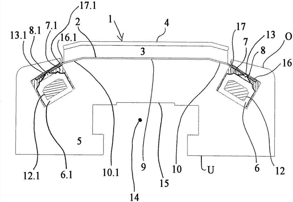
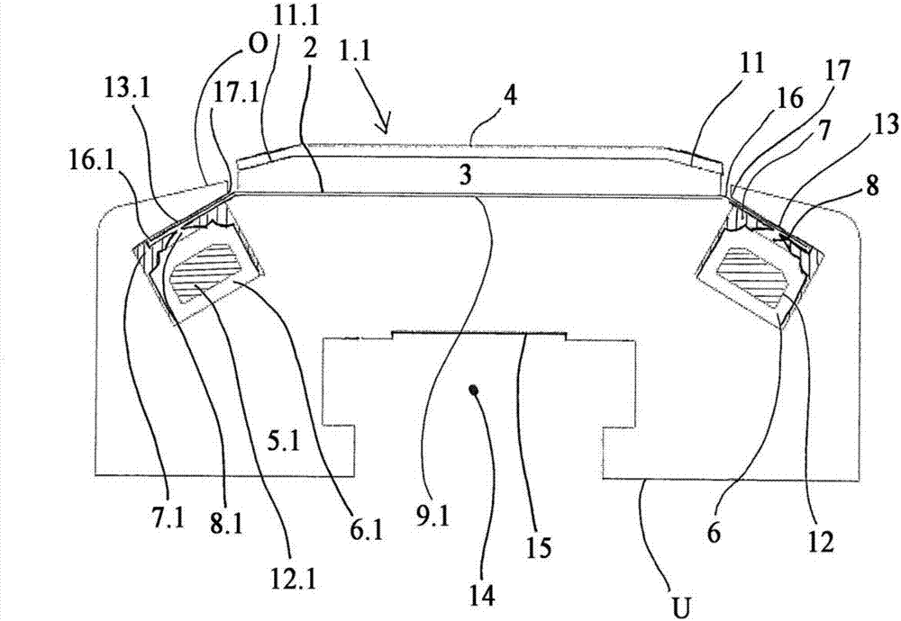
[0051] exist figure 1 A cross-sectional view of an embodiment of a grinding shoe receptacle 5 according to the invention with inserted grinding shoe 1 can be seen in .

[0052] The grinding shoe 1 consists of three layers. An intermediate material 3 is arranged in the middle. One side of the intermediate material 3 is a bracket 2 made of cardboard. The other side of the intermediate material 3 is coated with another layer, which is referred to as the belt motivator 4 . The intermediate material 3 and the belt actuator 4 do not completely cover the carrier 2, so that the first carrier strap 16 and the second carrier strap 16.1 of the carrier 2 remain uncovered.

[0053] The grinding shoe receptacle 5 has a contact surface 9 on the side O, against which the grinding shoe 1 rests. On the contact surface 9 a first bevel 10 is arranged on one side and a second bevel 10.1 is arranged on the other side. As a result, the contact surface 9 maintains the angled configuration. This...


PUM


Abstract

A sanding shoe (1, 1.1) for a belt grinding machine, consisting of a carrier (2), an intermediate material (3) and a sanding belt activator (4), wherein the carrier consists of a flexible material.

Description

technical field [0001] The invention relates to a grinding shoe according to the preamble of claim 1 , a device for securing a grinding shoe according to claim 3 , a grinding shoe shoe according to claim 9 and a grinding shoe according to claim 11 . method. Background technique [0002] Grinding shoes as well as grinding shoe supports or shoe receptacles are known from the prior art. However, these differ from the main features of the present invention. [0003] WO 2006 / 012843 A1 discloses a grinding shoe in which the receiving or supporting rail is made of metal. The same applies to the grinding shoe described in DE20315291U1. In this regard, the use of metals has many disadvantages, such as high thermal expansion, stiffness and other properties that negatively affect the grinding process. [0004] Grinding shoes using compressed air are also known, for example see DE 10 2005 054 213 A1. In this document, the so-called material web is inflated with compressed air, so t...

Claims


Application Information

Patent Timeline
Patent Type & Authority Applications(China)
IPC IPC(8): B24B21/08
CPCB24B21/08
Inventor 维斯图斯·维恩伯格斯安德里亚斯·科勒
Owner STEINEMANN TECH
Learn More