

Soft soil area roadbed widening structure and construction method thereof
A technology for roadbed and soft soil, applied in infrastructure engineering, roads, excavation, etc., can solve the problems of high design and construction level requirements, rising land acquisition and demolition costs, and increased foundation treatment costs, so as to reduce land acquisition and demolition costs, Beautiful appearance, the effect of reducing the processing cost
- Summary
- Abstract
- Description
- Claims
- Application Information
AI Technical Summary
Problems solved by technology
Method used
Image

Examples
Embodiment Construction
[0031] The present invention will be further described below in conjunction with accompanying drawings and examples of implementation.
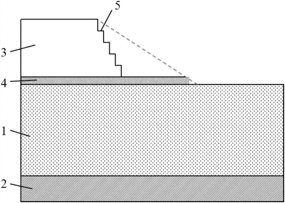
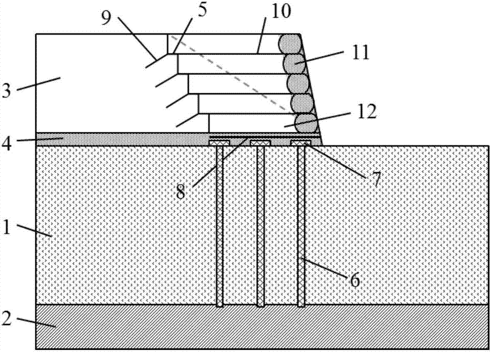
[0032] Such as figure 1 and figure 2As shown, the present invention provides a roadbed widening structure in soft soil area, comprising vertical pile body 6, reinforced gravel cushion (comprising gravel cushion 4 and geogrid or geocell 8), reinforced soil Retaining wall (composed of geogrid 10, bagged gravel 11 and filling soil 12) and connector 9. The vertical pile body 6 penetrates the soft ground layer 1 and is supported on the underlying bearing layer 2; the reinforced gravel cushion is laid on the top of the vertical pile body 6; the reinforced soil retaining wall is built on the reinforced gravel cushion Above; the connector 9 is set at the junction of the reinforced earth retaining wall and the old roadbed 3 and is connected to the reinforced earth retaining wall and the old roadbed 3 respectively.
[0033] The reinforced soil reta...
PUM
| Property | Measurement | Unit |
|---|---|---|
| Spacing | aaaaa | aaaaa |
| Diameter | aaaaa | aaaaa |
| Thickness | aaaaa | aaaaa |
Abstract
Description
Claims
Application Information