Vertically-controlled grouting steel perforated pipe pile foundation supporting beam retaining wall structure and construction method thereof

A technology of foundation joist retaining and vertical control, which is applied in basic structure engineering, excavation, construction, etc., can solve the problems of high requirements on construction conditions, high comprehensive cost, slow artificial hole digging speed, etc. Body strength, small footprint, and small construction machinery

Inactive Publication Date: 2017-07-28
RAILWAY ENG RES INST CHINA ACADEMY OF RAILWAY SCI
View PDF4 Cites 6 Cited by
  • Summary
  • Abstract
  • Description
  • Claims
  • Application Information

AI Technical Summary

Problems solved by technology

[0004] The purpose of the present invention is to provide a vertical control grouting steel pipe pile foundation joist retaining wall structure to solve the technical problems of high construction conditions, slow manual digging speed and high comprehensive cost existing in traditional pile foundation technology

Method used


Image

  • Vertically-controlled grouting steel perforated pipe pile foundation supporting beam retaining wall structure and construction method thereof
  • Vertically-controlled grouting steel perforated pipe pile foundation supporting beam retaining wall structure and construction method thereof
  • Vertically-controlled grouting steel perforated pipe pile foundation supporting beam retaining wall structure and construction method thereof

Examples


Embodiment 1

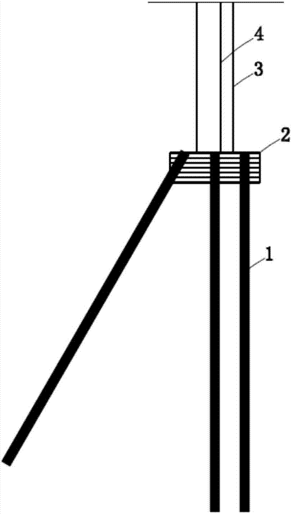
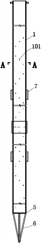
[0031] Such as figure 1 , figure 2 and image 3 As shown, the present invention provides a vertical control grouting steel flower tube pile foundation joist retaining wall structure, including steel flower tube boreholes arranged on the side slope, steel flower tubes 1 are arranged in the steel flower tube boreholes, steel flower tubes 1 Generally, a single 6m-long, Φ89×4.5mm seamless steel pipe is used, which can be lengthened or shortened according to the needs in the project. There are several secondary grouting holes 101 spirally arranged on the steel flower pipe 1, such as Figure 4 As shown, a secondary grouting hole 101 with a diameter of 8mm is drilled every 45° along the radial direction of the steel flower tube 1. The bottom of the steel flower tube 1 is provided with a blocking plate 5, and the side of the sealing plate 5 away from the steel flower tube 1 is fixedly connected. Triangular bracket 6, one end of the three edges of the triangular bracket 6 is set on ...

Embodiment 2

[0036] The present invention provides a vertical control grouting steel pipe pile foundation joist retaining wall structure, the structure is basically the same as the first embodiment, the difference is that on the basis of the first embodiment, the following features are added, making A further improvement has been made to improve the performance of the present invention.

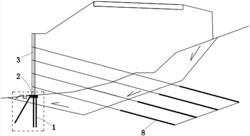
[0037] Such as figure 1 and figure 2 As shown, the retaining wall 3 is provided with a vertical rib concrete beam 4, and the retaining wall 3 is connected with a number of prestressed anchor cables 8, and the prestressed anchor cables 8 are anchored in the stable bedrock of the slope with an inclination angle of 10°-25°. , played a good reinforcement effect.

[0038] Taking the second-level slope work site as an example, the vertical height of the first-level side slope is H (m), the width of the top platform of the first-level side slope is ≥ 2m, and the first-level side slope adopts light-weight anch...

Embodiment 3

[0040] The invention provides a construction method for vertically controlling a grouted steel flower tube pile foundation joist retaining wall structure, which includes the following steps:

[0041] (1) Processing of steel floral tubes. There are several secondary grouting holes spirally arranged on the steel floral tubes. The diameter of the secondary grouting holes is 8mm, and the outer surface of the steel floral tubes is fixedly installed with primary grouting tubes;

[0042](2) Drilling, drilling vertically downward or obliquely on the slope, requiring the drilled hole to enter the weathered rock formation at least 4m, and the diameter of the drilled hole is 130mm;

[0043] (3) For the centering and lowering pipe, at least three centering steel bars are fixedly installed on the outer surface of the steel flower pipe. The surrounding is wrapped by grouting body to improve the anti-corrosion performance and tensile bearing capacity of the steel flower tube;

[0044] (4) O...


PUM


Abstract

The invention relates to a vertically-controlled grouting steel perforated pipe pile foundation supporting beam retaining wall structure and a construction method thereof and belongs to the technical field of capital construction. The vertically-controlled grouting steel perforated pipe pile foundation supporting beam retaining wall structure comprises a steel perforated pipe drill hole formed in a slope, the steel perforated pipe drill hole is internally provided with a steel perforated pipe, and the steel perforated pipe is spirally provided with a plurality of secondary grouting holes; the bottom of the steel perforated pipe is provided with a blocking plate, and the side, away from the steel perforated pipe, of the blocking plate is fixedly connected with a triangular supporting frame; the steel perforated pipe drill hole is internally provided with a grouting body, a pipe opening of the steel perforated pipe is provided with a sealing cover, the position of the pipe opening of the steel perforated pipe is provided with a concrete supporting beam, the concrete supporting beam is internally provided with a steel bar structure, the steel bar structure is welded to the steel perforated pipe, and the concrete supporting beam is provided with a retaining wall. By means of the vertically-controlled grouting steel perforated pipe pile foundation supporting beam retaining wall structure, the technical problems that a traditional pile foundation technology is high in construction condition requirement, low in manual hole digging speed and high in comprehensive cost are solved, and the vertically-controlled grouting steel perforated pipe pile foundation supporting beam retaining wall structure is widely applied to slope reinforcement engineering, such as roads, railways, mines and municipal administration.

Description

technical field [0001] The invention relates to the technical field of infrastructure construction, in particular to a vertically controlled grouting steel flower pipe pile foundation joist retaining wall structure and a construction method thereof, which is suitable for slope reinforcement projects of roads, railways, mines, municipalities, etc. Background technique [0002] The section of the pile foundation in the traditional pile joist retaining wall is large (the pile diameter is generally greater than 1m). If it is a round pile, a large drilling rig is required for construction, and the hillside area often does not have construction conditions, and large-scale mechanical construction is easy. The surrounding rock and soil cause further disturbance, resulting in a decrease in the strength of the rock and soil around the pile; if it is a square pile, it is necessary to manually dig holes to form the pile, which is slow and expensive, and the depth of the embedded bedrock ...

Claims


Application Information

Patent Timeline
Patent Type & Authority Applications(China)
IPC IPC(8): E02D17/20E02D15/04
CPCE02D15/04E02D17/207
Inventor 张玉芳徐一鸣陈记李健袁坤
Owner RAILWAY ENG RES INST CHINA ACADEMY OF RAILWAY SCI
Why Eureka
Try Eureka