Oil well casing gas pressurizing and collecting device

An oil well casing and gas pressurization technology, which is applied in the fields of production fluids, wellbore/well components, and earth-moving drilling, etc., can solve problems such as productivity decline, gas lock, and safety hazards, so as to eliminate energy waste and avoid environmental pollution. , the effect of preventing safety accidents

Active Publication Date: 2017-07-28
东营玺诺石油科技有限公司
View PDF6 Cites 3 Cited by
  • Summary
  • Abstract
  • Description
  • Claims
  • Application Information

AI Technical Summary

Problems solved by technology

At present, there are two treatment methods for oil well casing gas: one is to discharge into the atmosphere, which not only pollutes the environment, but also seriously wastes natural gas resources, and the other is that villagers living in the oil area connect the casing gas to their homes without permission, causing safety hazards and causing great harm to the environment. The comprehensive management of the oil area results in a large workload and management costs
The second is to use oil-casing connection for wells with large casing gas. Although this method can recover a certain amount of casing gas, it is restricted by the back pressure of the oil pipeline, causing the pressure of the casing to lower the liquid level of the oil layer and reduce the production capacity. prone to air lock
However, the existing bushing gas recovery device has a motor inside, which will generate electric sparks, and the bushing gas is petroleum gas, so it is flammable, explosive, and unsafe
At the same time, the existing casing gas recovery devices are all sealed and not easy to disassemble
In addition, the existing casing gas recovery device is bulky and inconvenient to carry and transport

Method used


Image

  • Oil well casing gas pressurizing and collecting device

Examples


Embodiment Construction

[0017] The present invention will be further described below with reference to the drawings and embodiments, and the content of the embodiments is not to limit the protection scope of the present invention.

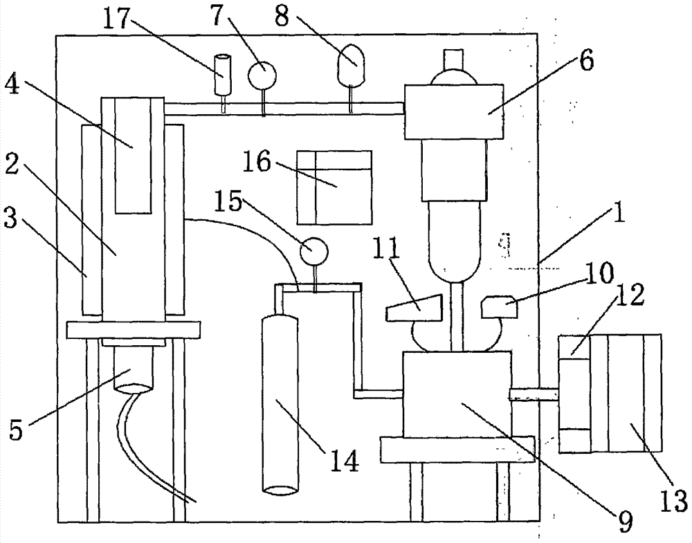
[0018] figure 1 The schematic diagram of the structure of the gas pressurized collection device for oil well casing of the present invention is shown. See figure 1 , The oil well casing gas pressurized collection device of the present invention includes a casing 1. The casing 1 is provided with an automatic gas-liquid separation pipe 2 connected with an oil well casing. The oil and gas from the oil well casing is separated from gas and liquid in the gas-liquid automatic separation pipe 2.

[0019] In the present invention, the gas-liquid automatic separation tube 2 is sheathed with an antifreeze thermostatic diversion tube 3. The antifreeze constant temperature guide tube 3 contains gas introduced from the compressor 9 described later, with a certain temperature, which pre...


PUM


Abstract

The invention relates to an oil well casing gas pressurizing and collecting device. The oil well casing gas pressurizing and collecting device comprises a shell internally provided with a gas-liquid automatic separation pipe; the gas-liquid automatic separation pipe is sleeved with an antifreezing constant-temperature diversion pipe; a filter element is arranged inside the gas-liquid automatic separation pipe, the lower end of the gas-liquid automatic separation pipe is connected with an automatic separation drainage device, and the upper end of the gas-liquid automatic separation pipe is connected with an inlet of a second-level pressure stabilizing separator; a casing pressure transmitter, a first vibration-resisting pressure gauge and a meter are arranged between the gas-liquid automatic separation pipe and the second-level pressure stabilizing separator; an outlet of the pressure stabilizing separator is connected with a compressor; the compressor is provided with an overpressure safety valve and a thermoswitch; an input shaft is connected with a belt wheel through a clutch; a gas outlet is connected with an oil collecting mains, and a second vibration-resisting pressure gauge is arranged between the gas outlet and the oil collecting mains; the gas outlet is connected with the interior of the antifreezing constant-temperature diversion pipe; a controller is arranged inside the shell; and the casing pressure transmitter, the thermoswitch and the clutch are all connected with the controller. The device is not provided with a motor, installed in front of an oil well reduction gearbox and driven by left power of a motor of a pumping unit, and is small in size, easy to install and high in safety; and operation cost is avoided, oil gas is recycled thoroughly, energy waste is avoided, the environment is protected, and pollution is completely eradicated.

Description

Technical field [0001] The invention belongs to the technical field of petroleum machinery, and relates to an oil and gas recovery device, in particular to an oil well casing gas pressurization collection device. Background technique [0002] The recovery of casing gas in oil wells is the main problem of environmental management in oil fields. As oilfield development enters the later stage, casing gas in oil wells is getting smaller and smaller, and the self-pressure of casing gas in oil wells can no longer enter the oil pipeline for recovery. At present, there are two ways to treat casing gas in oil wells: one is to discharge it into the atmosphere, which not only pollutes the environment, but also seriously wastes natural gas resources, and the other is that the villagers in the oil area privately connect the casing gas to their homes, causing safety hazards. The comprehensive management of the oil area has caused a large workload and management costs. The second is to use oi...

Claims


Application Information

Patent Timeline
Patent Type & Authority Applications(China)
IPC IPC(8): E21B43/16
CPCE21B43/16
Inventor 李西江张建国朱明军孙庆宇杨涛许军孙道军曲高川刘晓东王传喜王柯周吉利程元涛
Owner 东营玺诺石油科技有限公司
Why Eureka
Try Eureka