Cooling structure of top contra-rotating vortex of high temperature turbine moving blade

A technology of turbine blades and turbine blades, which is applied in the direction of blade support components, engine components, machines/engines, etc., to achieve the effects of enhancing heat transfer, alleviating local overheating areas, and reducing total pressure requirements

Inactive Publication Date: 2017-07-28
HARBIN INST OF TECH
View PDF6 Cites 1 Cited by
  • Summary
  • Abstract
  • Description
  • Claims
  • Application Information

AI Technical Summary

Problems solved by technology

[0005] The purpose of the present invention is to solve the deficiencies of the internal cooling structure of the existing turbine blades, and provide an internal cooling structure for the rotating vortex at the top of the high-temperature turbine blade

Method used


Image

  • Cooling structure of top contra-rotating vortex of high temperature turbine moving blade
  • Cooling structure of top contra-rotating vortex of high temperature turbine moving blade
  • Cooling structure of top contra-rotating vortex of high temperature turbine moving blade

Examples


specific Embodiment approach 1

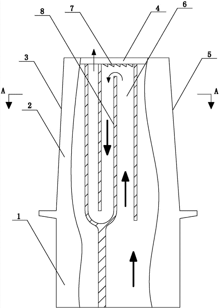
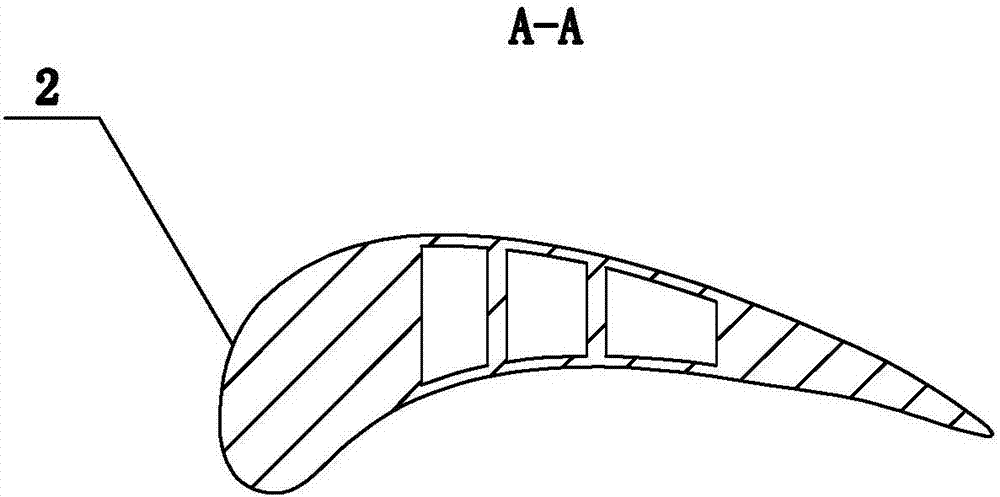
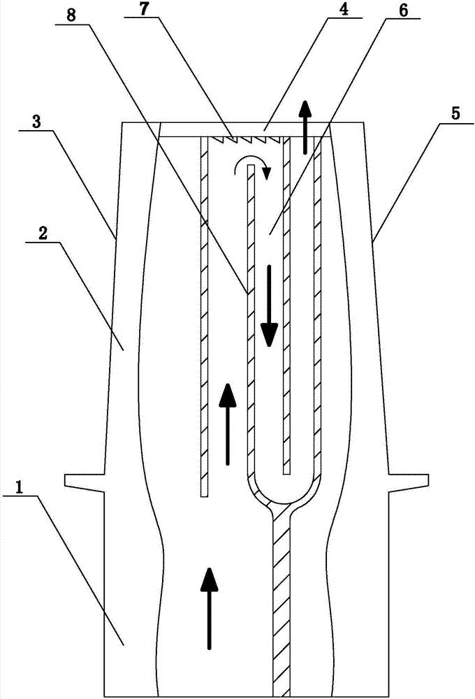
[0028] Specific implementation mode one: as figure 1 , figure 2 As shown, this embodiment discloses an internal cooling structure for the rotating vortex at the top of the high-temperature turbine blade, and its composition includes: turbine tenon 1, turbine blade body 2, turbine blade leading edge 3, turbine blade top cover 4, turbine blade The trailing edge 5 and the serpentine channel 6, the turbine tenon 1 is connected with the tail of the turbine blade body 2 as a whole, the top of the turbine blade body 2 is closed by the turbine blade top cover 4, and the turbine blade top cover 4 A cold air hole is provided, and the serpentine passage 6 is arranged inside the turbine blade body 2 and is located at the middle part of the chord length of the turbine blade, and the air outlet passage of the serpentine passage 6 communicates with the cold air hole; the top of the high-temperature turbine rotor blade The internal cooling structure of the counter-rotating vortex also inclu...

specific Embodiment approach 2

[0030] Specific implementation mode two: as figure 1 As shown, this embodiment is a further description of the specific embodiment 1. The serpentine channel 6 is composed of a plurality of partitions 8 arranged side by side and arranged in dislocation along the blade height direction, and forms a three or five Process serpentine cooling channels.

specific Embodiment approach 3

[0031] Specific implementation mode three: as figure 1 , Figure 5 , Image 6 As shown, this embodiment is a further description of specific embodiment 1 or 2. The counter-rotating vortex generator 7 includes multiple sets of counter-rotating vortex generator units, and each group of counter-rotating vortex generator units The bodies are all composed of a pair of triangular plates, and the plurality of groups of counter-rotating vortex generators are fixed vertically on the inner surface of the turbine blade top cover 4 in a matrix form, and each pair of triangular plates is arranged in a figure-eight shape. The narrow ends of each pair of triangular plates are set towards the side of the cooling hole (that is, the direction from the wide end to the narrow end of each pair of triangular plates is consistent with the flow direction of cold air), and the slopes of many pairs of triangular plates are all facing downward The lower ends of the slopes of multiple pairs of triangul...


PUM


Abstract

The invention discloses a cooling structure of a top contra-rotating vortex of a high temperature turbine moving blade, and belongs to the field of turbine heat transmission. The cooling structure of the top contra-rotating vortex of the high temperature turbine moving blade comprises a turbine tenon, a turbine blade body, a turbine blade front edge, a turbine blade top cover, a turbine blade tail edge, a serpentine channel and a contra-rotating vortex generator; the turbine tenon is connected with the tail of the turbine blade body into a whole; the top of the turbine blade body is closed through the turbine blade top cover; a cold air hole is formed in the turbine blade top cover; the serpentine channel is formed in the turbine blade body and is located at the chord-length middle part of a turbine blade; an air outlet channel of the serpentine channel communicates with the cold air hole; and the contra-rotating vortex generator is fixedly arranged on the internal surface of the turbine blade top cover and corresponds to the serpentine channel. The cooling structure is used for cooling the high temperature turbine moving blade, and has the characteristics that heat transfer is enhanced through forming the contra-rotating vortex and increasing a heat transfer area, and the increasing of the flow resistance is inhibited effectively.

Description

technical field [0001] The invention relates to a cooling structure for a high-temperature turbine rotor blade, in particular to an internal cooling structure for a rotating vortex at the top of a high-temperature turbine rotor blade, and belongs to the field of turbine heat transfer. Background technique [0002] The inlet temperature of modern gas turbine design is relatively high, and the gas temperature at the inlet of the turbine has reached 2200K, far exceeding the allowable temperature of the blade material, which will cause a large heat load on the blade surface. In order to ensure the safe operation of the gas turbine, in addition to increasing the temperature limit of the blade material and insulation layer, it is also necessary to cool the turbine blade. The cooling methods of modern high-temperature gas turbine blades are mainly divided into internal cooling and external cooling. Among them, the blade body of the turbine blade generally adopts a reciprocating fl...

Claims


Application Information

Patent Timeline
Patent Type & Authority Applications(China)
IPC IPC(8): F01D5/18
CPCF01D5/188
Inventor 罗磊王松涛赵志奇杜巍
Owner HARBIN INST OF TECH
Why Eureka
Try Eureka