Exhaust gas particulate matter trapping device and control method thereof

A technology of exhaust particles and exhaust gas, which is applied in the direction of electronic control of exhaust treatment devices, exhaust devices, noise reduction devices, etc. (The thermal stress of the filter element is large, so as to reduce the number of regenerations, promote collision and friction, and reduce the concentration

Active Publication Date: 2019-08-20
卢志旭
View PDF6 Cites 0 Cited by
  • Summary
  • Abstract
  • Description
  • Claims
  • Application Information

AI Technical Summary

Problems solved by technology

The existing particulate filter can filter most of the particles in the exhaust gas, and its particle capture efficiency is generally 70-90%. Increase, when the exhaust back pressure exceeds a certain value, the work of the diesel engine begins to deteriorate significantly, resulting in a decrease in engine power and economic performance, and the deposited particles must be removed in time to make the particle filter work normally, that is, the particle filter regeneration
The regeneration of the existing particulate filter is usually achieved by directly heating and burning the particles in the filter through an external heat source, which has problems such as large thermal stress on the filter body (filter element), short service life, and high energy consumption for regeneration. In addition, combustion Regeneration can only burn off the carbon particles inside the particle filter, but the ash trapped inside the particle filter cannot be burned and removed. It will accumulate in the particle filter and cause the pressure difference between the front and rear of the particle filter to rise, thereby affecting The working life of the particle filter requires manual cleaning of the particle filter. The general cleaning method is to disassemble the particle filter and clean the ash inside the particle filter by high-pressure gas blowback or water cleaning. drop, very inconvenient

Method used


Image

  • Exhaust gas particulate matter trapping device and control method thereof

Examples


Embodiment 1

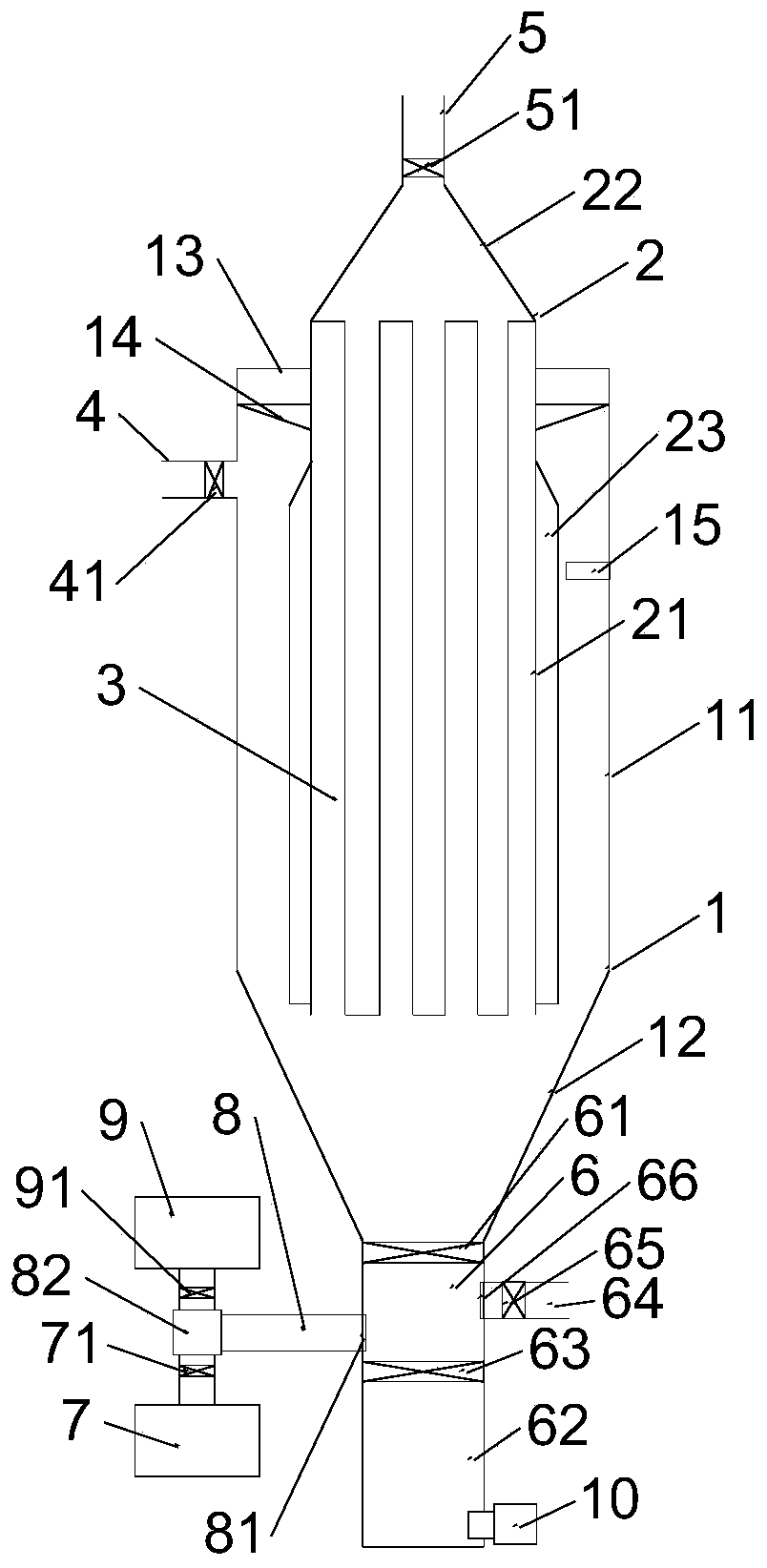
[0039] like figure 1 As shown, the present invention provides an exhaust particulate matter trapping device, comprising:

[0040] The first housing 1 is arranged vertically, and includes an integrally formed first cylindrical portion 11 and a first conical portion 12, the first cylindrical portion 11 is located directly above the first conical portion 12 and vertically penetrated ;

[0041] The second housing 2 is arranged vertically and includes an integrally formed second cylindrical portion 21 and a second conical portion 22. The second cylindrical portion 21 is located directly below the second conical portion 22 and is vertically connected. , the second cylindrical portion 21 is disposed inside the first cylindrical portion 11, and the upper portion of the second cylindrical portion 21 is connected to the upper portion of the first cylindrical portion 11 through a bearing 13;

[0042] A filter element 3, which is filled in the second cylindrical portion 21, the filter e...


PUM


Abstract

The invention discloses a tail gas particle trapping device which comprises a first shell, a second shell, a filter element, a gas inlet pipe, a first exhaust pipe and an ash discharge pipe. The second shell is driven by a motor to rotate, and the rotation direction is the same as the rotation direction of tail gas of the gas inlet pipe inside the first shell. The invention further discloses a control method of the tail gas particle trapping device. The tail gas particle trapping device has the advantages of being high in trapping efficiency, long in service life, low in regeneration energy consumption, capable of removing ash conveniently and the like.

Description

technical field [0001] The invention relates to the technical field of diesel vehicle tail gas treatment. More specifically, the present invention relates to an exhaust particulate matter trapping device and a control method thereof. Background technique [0002] In order to meet the increasingly stringent emission control targets, diesel vehicle exhaust after-treatment technology, as an important part of diesel engine emission control system, has attracted more and more attention. Particulate matter trap technology is considered to be the most direct and effective way to purify diesel engine particulate matter at present, and it is also one of the internationally commercialized diesel engine particulate post-treatment technologies. The existing particulate filter can filter most of the particles in the exhaust gas, and its particle capture efficiency is generally 70-90%. Increase, when the exhaust back pressure exceeds a certain value, the work of the diesel engine begins...

Claims


Application Information

Patent Timeline
Patent Type & Authority Patents(China)
IPC IPC(8): F01N3/023F01N9/00
CPCF01N3/0233F01N9/002Y02T10/40
Inventor 卢志旭
Owner 卢志旭
Why Eureka
Try Eureka