
Method for monitoring NOx sensors

A sensor, SCR catalyst technology, applied in electrical control, engine control, machine/engine, etc., can solve problems such as difficult monitoring and small emission measurement signals

Inactive Publication Date: 2017-07-28
ROBERT BOSCH GMBH
View PDF5 Cites 6 Cited by
  • Summary
  • Abstract
  • Description
  • Claims
  • Application Information

AI Technical Summary

Problems solved by technology

In particular, it is difficult to monitor NOx sensors positioned downstream of SCR catalytic converters or NSC catalytic converters (NOx storage catalytic converters, nitrogen oxide storage catalytic converters), since they are exposed to cleaned exhaust gases and emit and thus measure signal very small

Method used


Image

  • Method for monitoring NOx sensors
  • Method for monitoring NOx sensors
  • Method for monitoring NOx sensors

Examples


Embodiment Construction

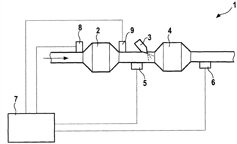
[0022] figure 1 A first exhaust gas aftertreatment system 1 (not shown) of a motor vehicle is schematically shown, in which a NOx sensor is monitored by means of a method according to an exemplary embodiment of the invention. The exhaust gas aftertreatment system 1 has an NSC / cDPF catalytic converter (NOx storage catalytic converter (NOx storage catalytic converter) and a coated diesel particulate filter) 2 , a reducing agent dosing point 3 , an SCR catalytic converter 4 , in the SCR The first NOx sensor 5 upstream of the SCR catalytic converter 4, the second NOx sensor 6 downstream of the SCR catalytic converter 4, the first temperature sensor 8 upstream of the NSC / cDPF catalytic converter 2, the The second temperature sensor 9 downstream of the NSC / cDPF catalytic converter 2 and the electronic controller 7 are connected. The controller 7 has data connections to the NOx sensors 5 , 6 and to the temperature sensors 8 , 9 .

[0023] figure 2 A second exhaust-gas aftertreatm...


PUM


Abstract

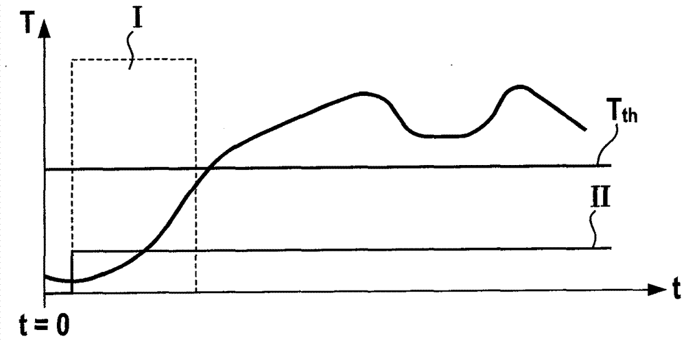
The invention relates to a method for monitoring NOx sensors (5, 6) in an exhaust gas aftertreatment system (1) of a motor vehicle, which has at least one SCR catalytic converter (4), wherein a signal of a NOx sensor (6) positioned at the downstream of the SCR catalytic converter (4) is compared with a NOx value at the upstream of the SCR catalytic converter (4) before the SCR catalytic converter (4) has exceeded a threshold temperature (Tth).

Description

technical field [0001] The invention relates to a method for monitoring a NOx sensor in an exhaust gas aftertreatment system of a motor vehicle. [0002] The invention also relates to a computer program which, when run on a computing device, implements each step of the method according to the invention; and a machine-readable storage medium storing said computer program. Finally, the invention relates to an electronic controller, which is designed to carry out the method according to the invention. Background technique [0003] Due to the introduction of ever more stringent limit values ​​for NOx emissions (nitrogen oxide emissions), very different exhaust gas aftertreatment technologies have been developed in order to control the NOx emissions in the exhaust gas of diesel motors. One of these technologies for exhaust gas aftertreatment is selective catalytic reduction in SCR catalysts. Here, the nitrogen oxides contained in the exhaust gas are reduced to nitrogen (N 2 )....

Claims


Application Information

Patent Timeline
IPC IPC(8): F01N11/00F01N9/00F01N3/20
CPCF01N3/208F01N9/00F01N11/00F01N2560/026F01N3/2066F01N11/002F01N13/008F01N2560/06F01N2560/14F01N2560/20F01N2610/00F01N2900/0601F01N2900/1402F01N2900/1404F01N2900/1602F02D41/06F02D41/1441F02D41/1461F02D41/1463F02D41/222F02D2200/0802F02D2250/36Y02T10/12Y02T10/40Y02A50/20
Inventor T.普菲斯特T.杭德勒
Owner ROBERT BOSCH GMBH
Learn More