Methods and system to prevent exhaust overheating

a technology of exhaust gas and exhaust gas, which is applied in the direction of electric control, speed sensing governor, instruments, etc., can solve problems such as damage to turbochargers or other components, and achieve the effects of lowering the exhaust gas temperature, reducing the air-to-fuel ratio of the engine, and reducing the peak combustion temperatur

Active Publication Date: 2014-03-06
GE GLOBAL SOURCING LLC
View PDF9 Cites 58 Cited by
  • Summary
  • Abstract
  • Description
  • Claims
  • Application Information

AI Technical Summary

Benefits of technology

[0004]In this way, when exhaust gas temperatures are elevated to temperatures that may degrade downstream components, the air-to-fuel ratio of the

Problems solved by technology

If the exhaust gas temperature reaches a high enough level,

Method used


Image

  • Methods and system to prevent exhaust overheating
  • Methods and system to prevent exhaust overheating
  • Methods and system to prevent exhaust overheating

Examples


Embodiment Construction

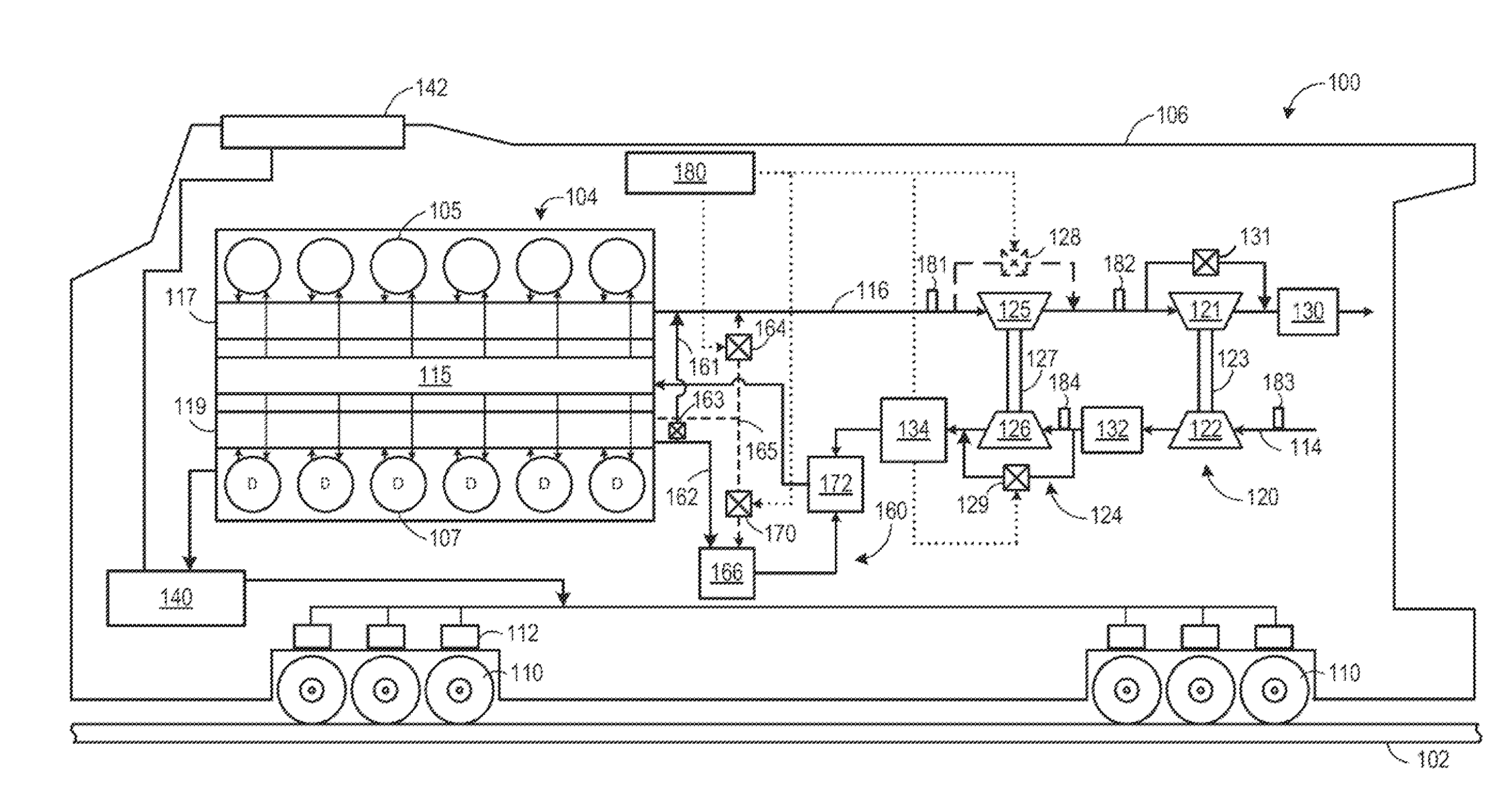
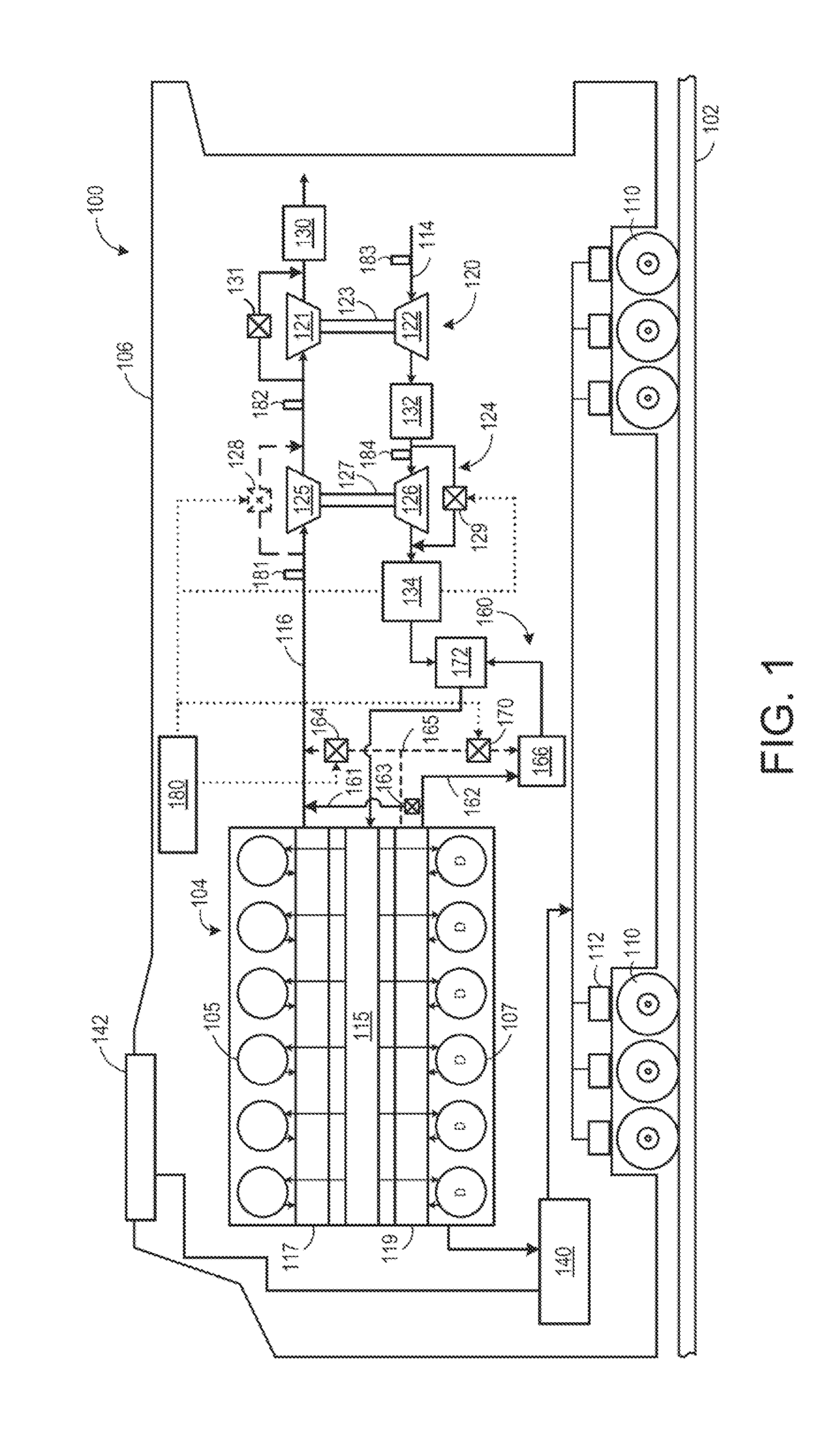
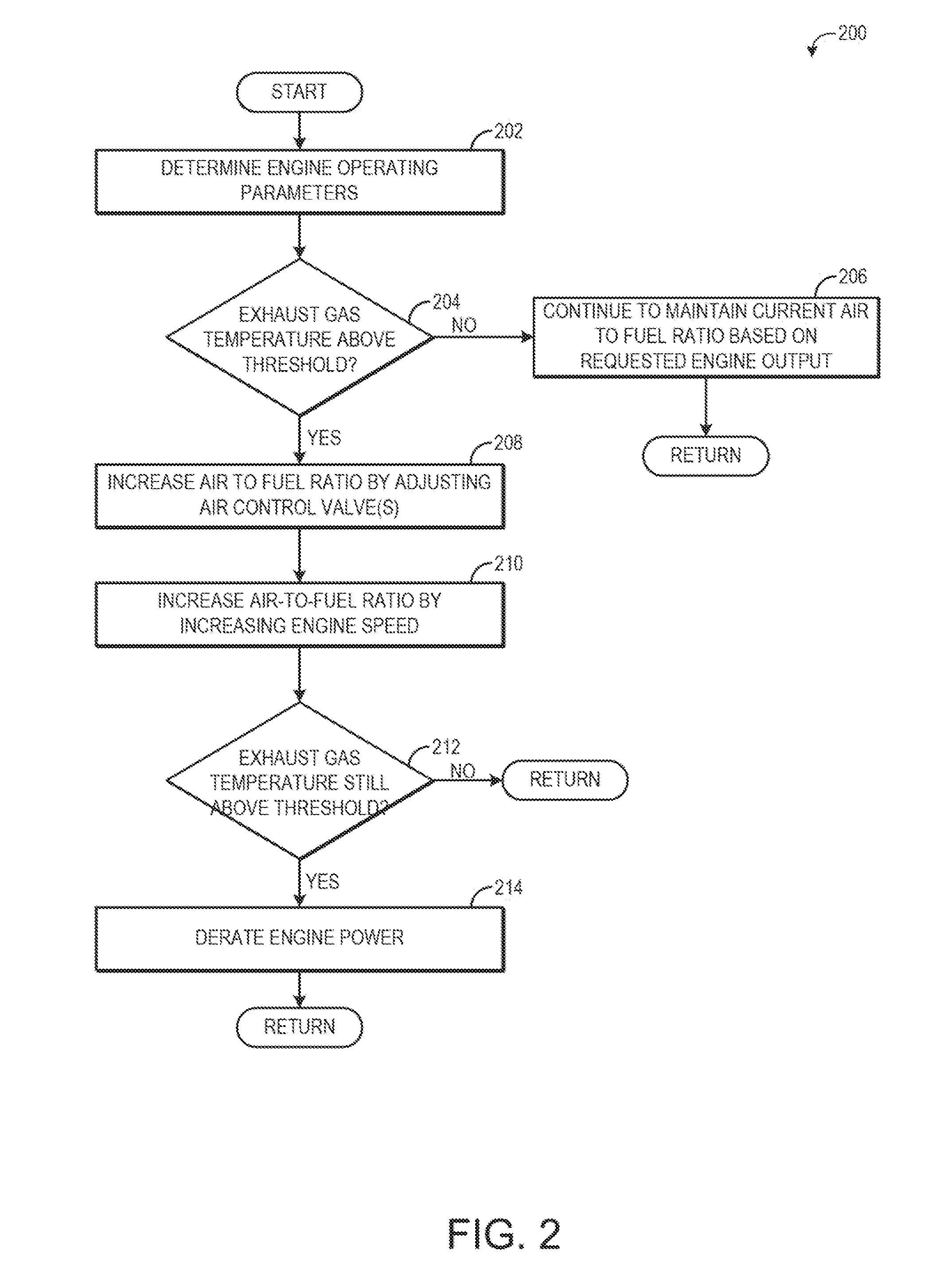
[0011]The following description relates to various embodiments for cooling exhaust gas. High exhaust gas temperatures may cause damage to a turbocharger or other components situated in an exhaust passage. To cool the exhaust, cylinder air-to-fuel ratio may be increased. By increasing the air-to-fuel ratio, more air is present in the cylinder, increasing the cylinder's heat capacity and lowering combustion temperatures. The air-to-fuel ratio may be increased without adjusting the amount of fuel delivered to the cylinders, for example by increasing engine speed or closing an air control valve, such as a high-pressure turbine bypass valve.

[0012]The approach described herein may be employed in a variety of engine types, and a variety of engine-driven systems. Some of these systems may be stationary, such as in a power-plant or generator-set application, while others may be on semi-mobile or mobile platforms. Semi-mobile platforms may be relocated between operational periods, such as mou...


PUM


Abstract

Various methods and systems are provided for lowering exhaust gas temperature. In one embodiment, a method comprises increasing an air-to-fuel ratio of an engine in response to an exhaust gas temperature exceeding a threshold temperature value to lower the exhaust gas temperature to a temperature below the threshold temperature value.

Description

FIELD[0001]Embodiments of the subject matter disclosed herein relate to an engine, engine components, and an engine system, for example.BACKGROUND[0002]Engine systems may be configured with a turbocharger or other exhaust components closely coupled to the cylinder exhaust outlets. If the exhaust gas temperature reaches a high enough level, damage to the turbocharger or other components may result.BRIEF DESCRIPTION[0003]In one embodiment, a method comprises increasing an air-to-fuel ratio of an engine in response to an exhaust gas temperature exceeding a threshold temperature value, to lower the exhaust gas temperature to a temperature below the threshold temperature value.[0004]In this way, when exhaust gas temperatures are elevated to temperatures that may degrade downstream components, the air-to-fuel ratio of the engine may be increased. By increasing the air-to-fuel ratio, peak combustion temperature may be lowered, thus lowering the exhaust gas temperature.[0005]It should be un...

Claims


Application Information

Patent Timeline
IPC IPC(8): F02D41/26F02B33/00F02B47/08F02B37/18F02D41/32F02M25/07
CPCF02B37/004F02B37/013F02B37/16F02B37/18F02D29/06F02D31/001F02D41/0007F02D41/0052F02D41/1446F02D2250/18F02D2250/24Y02T10/12Y02T10/40
Inventor HENRY, LUKELORINGER, DANIEL EDWARDMISCHLER, JAMES ROBERTBLYTHE, NEIL XAVIERMALONE, MATTHEW JOHNPOLKUS, GREG THOMAS
Owner GE GLOBAL SOURCING LLC
Why Eureka
Try Eureka