Eureka AIR delivers breakthrough ideas for toughest innovation challenges, trusted by R&D personnel around the world.

Calibration method of projector

A calibration method and projector technology, applied in the field of projector calibration, can solve problems such as high cost and troublesome calibration board production

Active Publication Date: 2017-07-28
GUANGDONG UNIV OF TECH +1
View PDF5 Cites 30 Cited by
  • Summary
  • Abstract
  • Description
  • Claims
  • Application Information

AI Technical Summary

Problems solved by technology

[0006] However, whether it is the phase method with high precision or the most widely used reverse projection method, the calibration of the projector under a certain projection format must be equipped with a calibration plate of a specific size. Configure multiple calibration boards, and the production of calibration boards is troublesome and costly

Method used


Image

  • Calibration method of projector
  • Calibration method of projector
  • Calibration method of projector

Examples


Embodiment Construction

[0045] The core idea of ​​the present invention is to provide a projector calibration method, which enables the three-dimensional structured light scanning measurement system to measure workpieces of different scales without changing multiple calibration plates, and is suitable for three-dimensional detection of various micro components of different sizes.

[0046] The following will clearly and completely describe the technical solutions in the embodiments of the present invention with reference to the accompanying drawings in the embodiments of the present invention. Obviously, the described embodiments are only some, not all, embodiments of the present invention. Based on the embodiments of the present invention, all other embodiments obtained by persons of ordinary skill in the art without making creative efforts belong to the protection scope of the present invention.

[0047] The first projector calibration method provided by the embodiment of this application is as follo...


PUM


Abstract

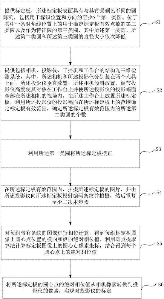
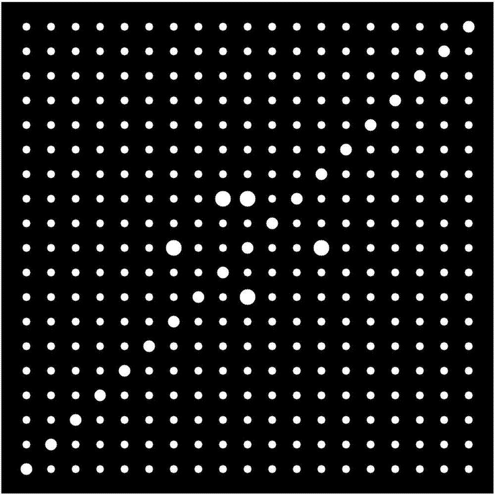
The invention discloses a calibration method of a projector. The calibration method comprises steps of providing a calibration plate; providing a structure optical three-dimensional detection system; using a first type of circle to right the calibration plate; in an effective range of the calibration plate, shooting pictures on the calibration plate, projecting coding strips to the calibration plate and shooting through the projector, and repeating the step for at least twice; carrying out phase position calculation on each group of images with strips to obtain horizontal and longitudinal absolution phase position values of centre point positions of each group of the calibration plate images, using a circular point extraction algorithm to calculate center point pixel coordinates on the calibration plate images and combining the horizontal and longitudinal absolution phase position values and the center point pixel coordinates to obtain an absolute phase position value of each centre point; and converting the absolute phase position value of each centre point of the calibration plate into pixels of the projector from pixels of a camera, thereby achieving calibration of the projector. According to the invention, the three-dimensional structure optical scanning measurement system is enabled to achieve measurement of workpieces in different sizes with no need to change various kinds of calibration plates, and the calibration method is suitable for three-dimensional detection of micro elements in different sizes.

Description

technical field [0001] The invention belongs to the technical field of three-dimensional optical measurement, in particular to a projector calibration method. Background technique [0002] With the rapid development of microelectronics manufacturing technology, various micro-miniature components, such as semiconductor devices, optoelectronic components and MEMS, have been mass-produced in industry and widely used in high-end electronic products and precision instruments. The precision manufacturing of such tiny components has high precision, and the three-dimensional detection of their shape accuracy is a major challenge. [0003] Structured light measurement technology has the advantages of non-contact, full-field scanning, high precision, and fast speed. It has been widely used in industrial inspection, machine vision, digitalization of cultural relics, and medicine. Among the existing structured light measurement systems, the structured light 3D measurement system consis...

Claims


Application Information

Patent Timeline
IPC IPC(8): G01B11/25
CPCG01B11/254
Inventor 高健张观锦林辉陈新陈云汤晖贺云波张昱杨海东
Owner GUANGDONG UNIV OF TECH
Why Eureka
Eureka Blog
Learn More