Internet-of-things aquatic product culturing monitoring system with electricity quantity detection function
A technology for aquaculture and electricity detection, which is applied in the direction of measuring electric variables, measuring electricity, measuring devices, etc., can solve problems such as the inability to effectively monitor the remaining electricity of the solar power generation system, battery over-discharge and loss of electricity, and paralysis of the breeding system to ensure continuous Effective work, avoid power loss, and avoid damage
- Summary
- Abstract
- Description
- Claims
- Application Information
AI Technical Summary
Problems solved by technology
Method used
Image
Examples
Embodiment 1
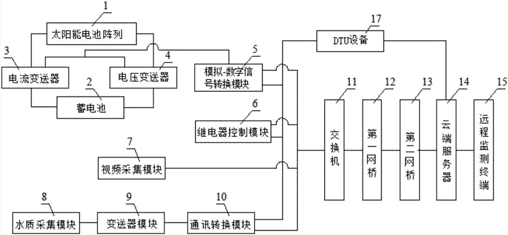
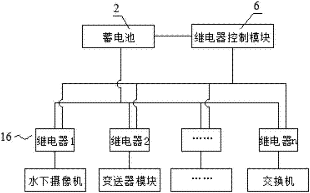
[0021] Such as figure 1 with 2As shown, the Internet of Things aquaculture monitoring system with power detection function involved in this embodiment includes a solar cell array 1, a storage battery 2, a current transmitter 3, a voltage transmitter 4, an analog-to-digital signal conversion module 5, and a relay control Module 6, relay 16, video acquisition module 7, water quality acquisition module 8, transmitter module 9, communication conversion module 10, switch 11, first network bridge 12, second network bridge 13, cloud server 14 and remote monitoring terminal 15 The voltage transmitter 4 and the current transmitter 3 are connected between the solar cell array 1 and the storage battery 2 and are respectively used to measure the charging and discharging voltage and the charging and discharging current of the storage battery 2, and the voltage transmitter 4 is used to collect the collected The DC voltage is converted into a current signal according to a certain ratio and ...
Embodiment approach
[0022] As another embodiment, the Internet of Things aquaculture monitoring system with power detection function also includes a DTU device 17, the analog-to-digital signal conversion module 5, the relay control module and the communication conversion module are all connected to the DTU device 17, and the DTU device 17 passes The GPRS wireless network is connected to the cloud server 14, and the collected data is transmitted remotely to the remote monitoring terminal 15, and the control commands issued by the remote monitoring terminal 15 are transmitted to the corresponding equipment. The DTU equipment 8 is a remote information sending and receiving terminal, which is based on The wireless transmission terminal of GPRS technology, after the DTU equipment 8 collects the signal, transmits the signal to the cloud server 9 through GPRS wirelessly. This design can save power by turning off cameras, bridges and switches that consume a lot of power when there is no need for video cap...
PUM
 Abstract
Description
Claims
Application Information
 - R&D
- Intellectual Property
- Life Sciences
- Materials
- Tech Scout
- Unparalleled Data Quality
- Higher Quality Content
- 60% Fewer Hallucinations
Browse by: Latest US Patents, China's latest patents, Technical Efficacy Thesaurus, Application Domain, Technology Topic, Popular Technical Reports.
© 2025 PatSnap. All rights reserved.Legal|Privacy policy|Modern Slavery Act Transparency Statement|Sitemap|About US| Contact US: help@patsnap.com


