Optical device, light source device and projector

A technology of optical devices and light source devices, applied in optics, projection devices, instruments, etc., can solve the problems of increased noise, faster blade speed, and large and larger heat sinks, so as to achieve the effect of light weight

Active Publication Date: 2019-03-12
SEIKO EPSON CORP
View PDF7 Cites 1 Cited by
  • Summary
  • Abstract
  • Description
  • Claims
  • Application Information

AI Technical Summary

Problems solved by technology

[0007] However, in the technique disclosed in Patent Document 1, the fins of the heat sink protrude long toward the side opposite to the phosphor plate, and there is a problem of increasing the size of the device.
[0008] In addition, it is also conceivable that it is difficult for the heat sink described in Patent Document 2 to fully utilize the flow of air generated by the rotation, resulting in an increase in the number of rotations of the fins and an increase in the size of the heat sink.
There is such a problem: when the rotation speed of the heat sink is increased, the noise will increase due to frictional wind noise, and when the heat sink is enlarged, the size and weight of the light source device will increase.

Method used


Image

  • Optical device, light source device and projector
  • Optical device, light source device and projector
  • Optical device, light source device and projector

Examples


Embodiment Construction

[0049] Hereinafter, the projector of this embodiment will be described with reference to the drawings.

[0050] [Outline structure of the projector]

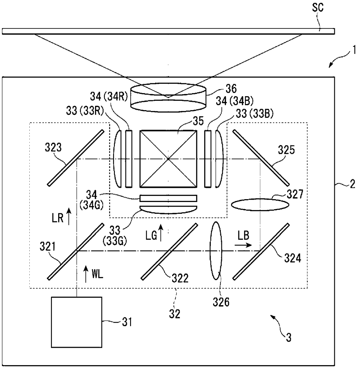
[0051] figure 1 It is a schematic diagram showing the structure of the projector 1 of this embodiment.

[0052] The projector 1 of the present embodiment is a display device that modulates the light emitted from the illuminating device 31 installed inside to form an image corresponding to image information, and enlarges and projects the image onto a screen SC as a projection surface.

[0053] Such as figure 1 As shown, the projector 1 has an outer casing 2 and an optical unit 3 housed in the outer casing 2. In addition, although not shown, the projector 1 further includes a control device that controls the projector 1, a cooling device that cools cooling objects such as optical components, and a power supply device that supplies power to electronic components.

[0054] [Structure of Optical Unit]

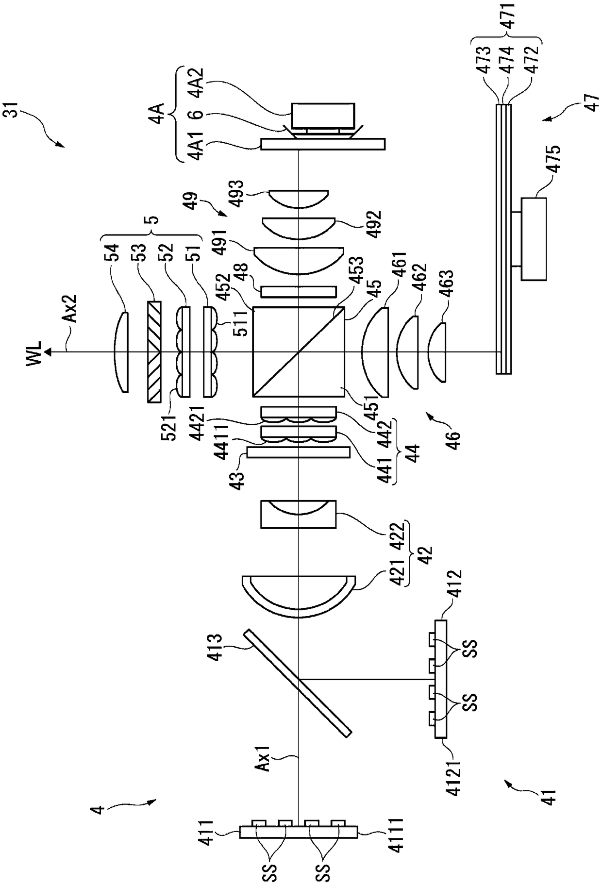
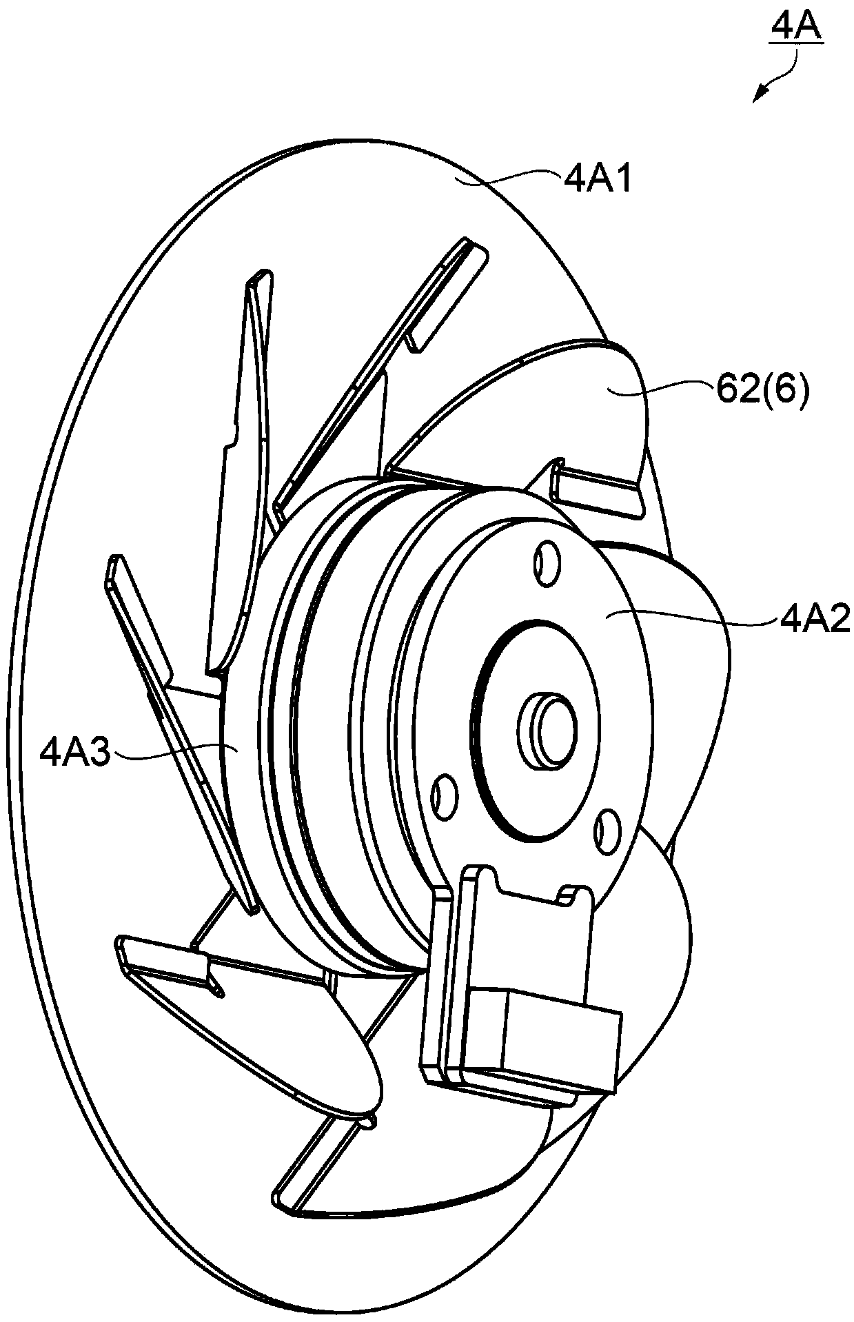
[0055] The optical unit 3 has an illumin...


PUM


Abstract

An optical device, a light source device, and a projector are provided. The optical device capable of inhibiting optical element degradation and achieving long service lifetime is provided, and includes a reflecting plate (4A1) and a rotation member (6) that dissipates the heat of the reflecting plate (4A1). The rotation member (6) includes a base portion (61) placed on the reflecting plate (4A1) and a plurality of blade portions (62) that project to the side opposite to the base portion (61). The plurality of blade portions (62) each includes an inclined portion (62a) that is inclined with respect to the base portion (61).

Description

Technical field [0001] The invention relates to an optical device, a light source device and a projector. Background technique [0002] Conventionally, there has been known a projector that modulates light emitted from a light source based on image information and projects an image on a projection surface such as a screen. The optical element in the projector generates heat due to the light from the light source. Therefore, techniques for cooling the optical element have been proposed (for example, refer to Patent Document 1 and Patent Document 2). [0003] Patent Document 1 describes a light source device having an excitation light source unit that emits excitation light and a fluorescent light emitting unit. The fluorescent light-emitting unit has a phosphor plate having a phosphor layer, a substrate on which the phosphor plate is placed, and a heat sink. The phosphor plate is irradiated with excitation light emitted from the excitation light source section, and emits fluoresce...

Claims


Application Information

Patent Timeline
Patent Type & Authority Patents(China)
IPC IPC(8): G03B21/16
CPCG03B21/16
Inventor 青木繁和
Owner SEIKO EPSON CORP
Why Eureka
Try Eureka