
Three-plunger hydraulic diaphragm reciprocating pump

A reciprocating pump and hydraulic technology, which is applied in the direction of pumps, liquid variable displacement machines, pumps with flexible working elements, etc., can solve the problems of large transition plate volume, etc., and achieve the effects of compact size, reduced quantity, and simplified processing technology

Active Publication Date: 2017-08-01
DEPAMU HANGZHOU PUMP TECH
View PDF5 Cites 2 Cited by
  • Summary
  • Abstract
  • Description
  • Claims
  • Application Information

AI Technical Summary

Problems solved by technology

[0006] In view of the above problems, the present invention proposes a three-plunger hydraulic diaphragm reciprocating pump, which solves the defect that the existing three-plunger hydraulic diaphragm reciprocating pump is affected by the diameter of the diaphragm pump head and causes a large volume of the transition plate

Method used


Image

  • Three-plunger hydraulic diaphragm reciprocating pump
  • Three-plunger hydraulic diaphragm reciprocating pump
  • Three-plunger hydraulic diaphragm reciprocating pump

Examples


Embodiment Construction

[0023] Below in conjunction with each accompanying drawing, the present invention is described in detail.

[0024] The front and rear in the present invention are defined according to the front and rear of the installation position, wherein the side close to the power end is the front end, and the opposite is the rear end.

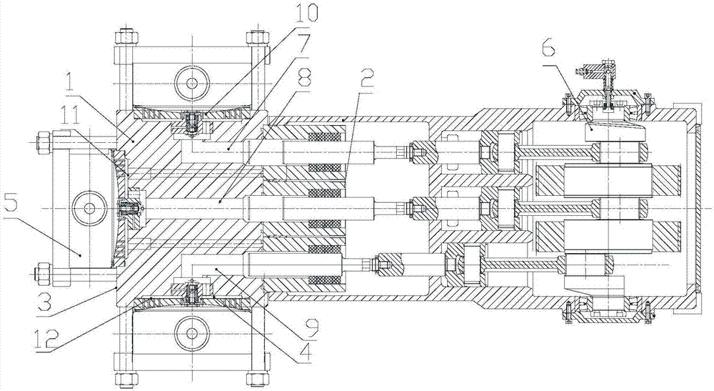
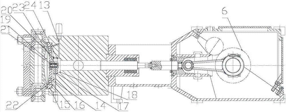
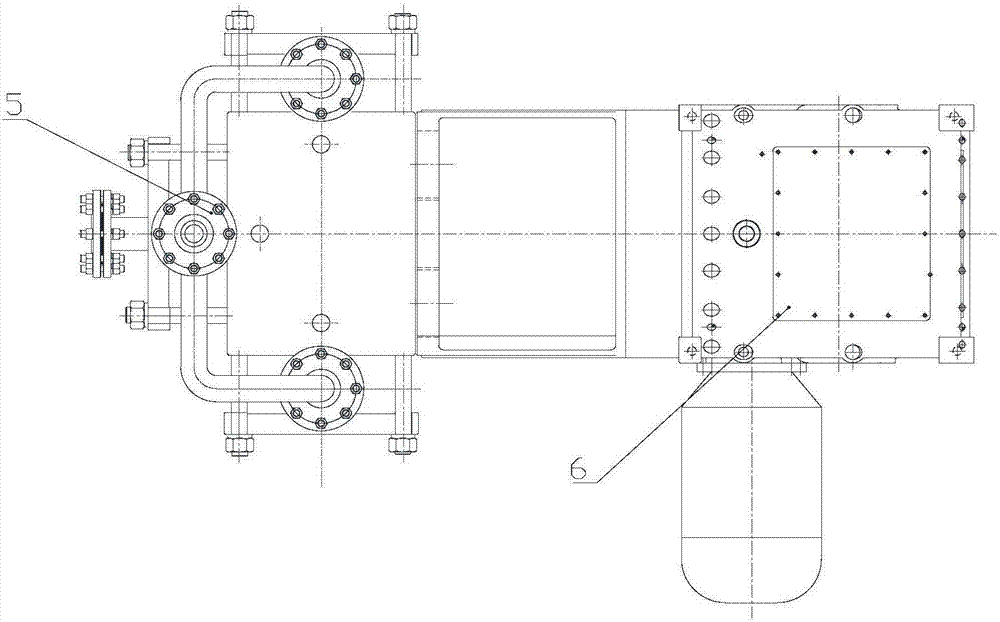
[0025] The invention discloses a three-plunger hydraulic diaphragm reciprocating pump (see attached figure 1 ), including: a transition plate 1 having a front end face 2, a rear end face 3 and several side faces 4, three pump heads 5 and a power end 6; the power end 6 is used to provide power to the pump head 5 through the transition plate 1; The front end of the transition plate 1 is provided with a first hydraulic passage 7, a second hydraulic passage 8 and a third hydraulic passage 9 arranged side by side, and the first hydraulic passage 7, the second hydraulic passage 8 and the third hydraulic passage 9 are all The power end 6 is connected through the...


PUM


Abstract

The invention discloses a three-plunger hydraulic diaphragm reciprocating pump. The pump comprises a transition plate having a front end surface, a back end surface and multiple side surfaces, three pump heads and a power end; a first hydraulic passage, a second hydraulic passage and a third hydraulic passage which are arranged in parallel are arranged at the front end of the transition plate and communicate with the power end through cylinder sleeves; a first pump head connection port, a second pump head connection port and a third pump head connection port which are connected with the three pump heads are formed in the back end of the transition plate; the second pump head connection port is located in the back end surface of the transition plate; and the first pump head connection port and the third pump head connection port are located in the opposite side surfaces of the back end of the transition plate. The novel three-plunger hydraulic diaphragm reciprocating pump is designed, the three hydraulic diaphragm pump heads are arranged in the shape of a left-center-right U-shaped surface, the transverse size is substantially reduced, the U-shaped-surface transition connecting plate can be machined by the aid of a lathe, the distance of communicating runners for the pump heads and the cylinder sleeves is shortened, and the machining technology is simplified.

Description

technical field [0001] The invention relates to the field of manufacturing hydraulic diaphragm reciprocating pumps, in particular to a three-plunger hydraulic diaphragm reciprocating pump. Background technique [0002] Three-plunger hydraulic diaphragm reciprocating pump is characterized by large flow, high working pressure, small flow pulsation, and flow is basically not affected by pressure. The hydraulic diaphragm type reciprocating pumping medium can achieve zero leakage, and has excellent anti-corrosion and explosion-proof characteristics. Safe and reliable in use, green and environmentally friendly, it is widely used in energy, petrochemical, thermal power, chemical, environmental protection and other industries. [0003] The working principle of the three-plunger hydraulic diaphragm reciprocating pump is: the gear shaft driven by the motor meshes with the gear on the crankshaft, the crankshaft obtains a decelerated circular motion, and converts the rotational motion ...

Claims


Application Information

Patent Timeline
Patent Type & Authority Applications(China)
IPC IPC(8): F04B43/06
CPCF04B43/06
Inventor 周良
Owner DEPAMU HANGZHOU PUMP TECH
Learn More