
Hydrodynamic device capable of precisely controlling pressure and boosting method

A technology of fluid power and precise control, which is applied in the direction of fluid pressure actuators, fluid pressure converters, servo motors, etc., and can solve the problem of inability to meet the requirements of precise pressurization and precise depressurization, air compressors with large vibration and noise, and one-way Problems such as large single minimum passage of the valve achieve the effect of small vibration, reduced noise and vibration, and low noise

Active Publication Date: 2017-08-01
INST OF GEOCHEM CHINESE ACADEMY OF SCI
View PDF10 Cites 7 Cited by
  • Summary
  • Abstract
  • Description
  • Claims
  • Application Information

AI Technical Summary

Problems solved by technology

[0005] (1) The high-pressure liquid booster pump is generally an air-driven pump. The power of the pneumatic fluid booster pump comes from compressed air, and the compressed air requires an air compressor. The vibration and noise of the general air compressor are relatively large. The press also does not meet the requirements and cannot be installed near the spectrometer
[0006] (2) The single-stroke displacement of general liquid booster pumps is large, and the single-stroke displacement of liquid booster pumps with small single-stroke displacements is 0.4 mL, which cannot meet the requirements for pressure vessels with a volume of only a few milliliters to tens of milliliters. Precise pressurization and depressurization requirements
[0007] (3) The high-pressure gas booster pump is generally an air-driven pump. The power of the pneumatic booster pump comes from compressed air, and the compressed air requires an air compressor. The vibration and noise of the general air compressor are relatively large, even if the silent air compressor The machine cannot meet the requirements and cannot be installed near the spectrometer
[0008] (4) The general high-pressure pneumatic booster pump has a large single-stroke displacement, and the gas booster pump with a small single-stroke displacement has a single-stroke displacement of 19.7 mL, which cannot meet the requirements of precise pressurization and decompression
[0009] (5) Generally, booster pumps for reciprocating pressurization need to use check valves. Due to the structural characteristics of check valves, the single minimum throughput of check valves is generally relatively large, which cannot meet the requirements of precise pressurization and precise depressurization. Requirements, and due to the existence of the check valve, the booster pump cannot be used for step-down control
[0010] (6) Most of the liquid and gas decompression schemes widely used at present are to directly open the pressure relief valve for pressure relief, or to depressurize through the pressure relief valve, but the mechanical structure of the pressure relief valve determines the decompression The accuracy of valve control and pressure reduction is poor. At present, there is no suitable pressure reducing valve that can achieve a pressure control accuracy of 0.1 MPa within the pressure range of 0-100 MPa and the flow rate is small.

Method used


Image

  • Hydrodynamic device capable of precisely controlling pressure and boosting method
  • Hydrodynamic device capable of precisely controlling pressure and boosting method

Examples


Embodiment 1

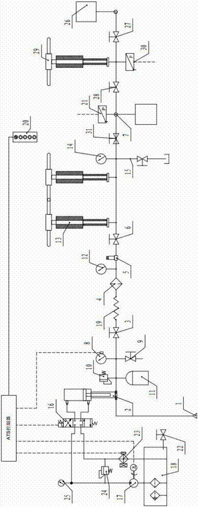
[0039] Embodiment 1: as Figure 1-Figure 2 As shown, a fluid power device that can precisely control the pressure includes a gas booster pipeline system and a liquid booster pipeline system connected in parallel to the pressure port 7. The gas booster pipeline system includes gas cylinders 1, Booster pump 2, medium pressure shut-off valve 3, filter 4, pressure reducing valve 5, high pressure shut-off valve 3 6 and high pressure shut-off valve 4 31. The pressure valve 9 and the high-pressure gas storage tank 11, the pipeline between the high-pressure shut-off valve 3 6 and the high-pressure shut-off valve 4 31 are connected with a gas high-pressure booster cylinder 13 and a high-pressure pressure relief valve 15, and the liquid booster pipeline system includes regular connections connected in sequence. Pressurized liquid container 26, liquid high-pressure shut-off valve one 27 and liquid high-pressure shut-off valve two 28, liquid booster cylinder 29 is connected on the pipelin...


PUM


Abstract

The invention discloses a hydrodynamic device capable of precisely controlling pressure and a boosting method. The hydrodynamic device comprises a gas boosting pipeline system and a liquid boosting pipeline system which are connected to a pressure port in parallel, wherein the gas boosting pipeline system comprises a gas cylinder, a booster pump, a medium pressure stop valve, a filter, a pressure reducing valve, a high pressure stop valve III and a high pressure stop valve IV which are sequentially connected; a medium pressure relief valve and a high pressure gas storing tank are connected to a connecting pipeline between the booster pump and the medium pressure stop valve; a gas high-pressure boosting cylinder and a high-pressure relief valve are connected to a pipeline between the high pressure stop valve III and the high pressure stop valve IV; the liquid boosting pipeline system comprises a normal pressure liquid container, a liquid high pressure stop valve I and a liquid high pressure stop valve II which are sequentially connected; and a liquid boosting cylinder is connected to a pipeline between the liquid high pressure stop valve I and the liquid high pressure stop valve II. Confining pressure can reach 100MPa, the pressure output range is large, the gas leakage quantity is small, the confining pressure is independently regulated, the fluctuation is small, and the pressure is controlled in a segmented manner. In a range between 0.1MPa and 100MPa, the pressure control precision is 0.1MPa in pressure raising and lowering processes. The pressure control precision is high, the vibration is small, and the noise is low.

Description

technical field [0001] The invention belongs to the technical field of high-temperature and high-pressure experimental devices, and in particular relates to a fluid power device and a pressurization method capable of precisely controlling pressure. Background technique [0002] In the process of simulating changes in the physical and chemical properties of deep rocks in the earth, many experimental devices for high temperature and high pressure have been developed. In order to obtain the property changes of certain rocks and minerals under different pressures, it is often necessary to precisely control the pressure of the experimental device. For example, when it is necessary to provide high-pressure water fluid to the high-temperature and high-pressure experimental device and precisely control the pressure in the high-temperature and high-pressure experimental device, a set of high-pressure liquid booster piping system is required. As another example, in a high-temperature...

Claims


Application Information

Patent Timeline
Patent Type & Authority Applications(China)
IPC IPC(8): F15B13/044F15B11/08F15B3/00
CPCF15B3/00F15B11/08F15B13/044
Inventor 李胜斌李和平陈琳刘礼宇周宏斌
Owner INST OF GEOCHEM CHINESE ACADEMY OF SCI
Learn More