
fuel atomizing nozzle

A technology of fuel atomization and nozzles, which is applied in the direction of burners, lighting and heating equipment, etc. It can solve the problems of small adjustment range, scattered oil mist spray, and difficult adjustment of air flow, so as to improve the atomization effect and simplify the atomization process , the effect of reducing the gas-liquid ratio

Active Publication Date: 2019-02-12
AECC HUNAN AVIATION POWERPLANT RES INST
View PDF7 Cites 1 Cited by
  • Summary
  • Abstract
  • Description
  • Claims
  • Application Information

AI Technical Summary

Problems solved by technology

[0009] 1) The bubble atomization process is complicated, and three-stage air mixing is used, resulting in a longer nozzle length
[0010] 2) It is difficult to adjust the gas-liquid ratio, and it is difficult to meet the oil-gas ratio adjustment needs of the multi-working condition combustion chamber
The oil and gas ratio of this nozzle is relatively high, and the air flow is difficult to adjust: there is only one air inlet, and the adjustment range of the air inlet pressure is small under the premise of ensuring the bubble atomization effect (the air pressure should be greater than the oil pressure, and less than the oil pressure. may cause fuel to enter the gas circuit from the mixing chamber)
[0011] 3) Nozzle spray cone angle and oil mist spray shape are difficult to control
The nozzle belongs to the external ultrasonic atomizer. The oil mist is sprayed directly into the boiler after ultrasonic atomization. The spray of oil mist is scattered and not concentrated enough. Although it can meet the use of large-sized boilers, it is not suitable for combustion heaters. For head oil The need for fog distribution

Method used


Image

  • fuel atomizing nozzle
  • fuel atomizing nozzle
  • fuel atomizing nozzle

Examples


Embodiment Construction

[0047] Example embodiments will now be described more fully with reference to the accompanying drawings. Example embodiments may, however, be embodied in many forms and should not be construed as limited to the embodiments set forth herein; rather, these embodiments are provided so that this disclosure will be thorough and complete, and will fully convey the concept of example embodiments to those skilled in the art. The same reference numerals in the drawings denote the same or similar structures, and thus their detailed descriptions will be omitted.

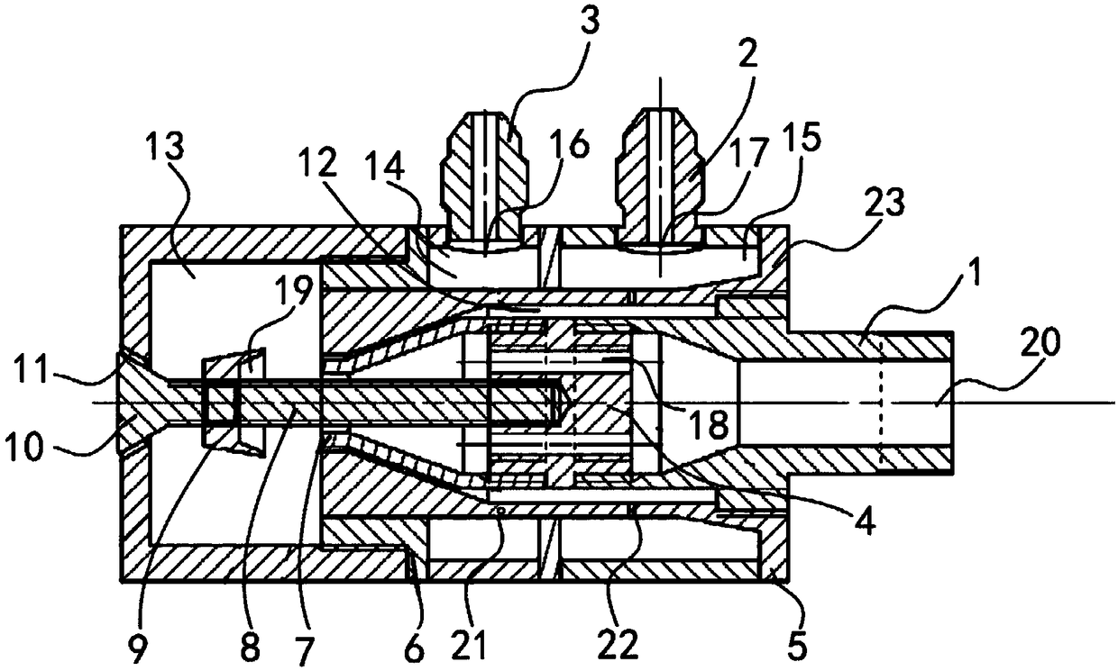
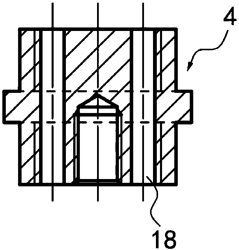
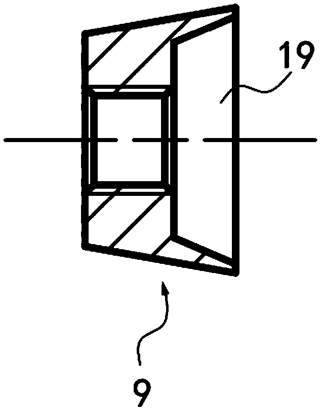
[0048] refer to figure 1 and Figure 5 , according to a specific embodiment of the present invention, wherein the fuel atomizing nozzle can be applied to a combustion heater. The fuel atomizing nozzle may include an auxiliary air intake chamber 15, a fuel oil chamber 14 and a secondary mixing chamber 13 which are arranged in sequence but are not communicated with each other, wherein the auxiliary air intake chamber 15 and th...


PUM


Abstract

The invention discloses a fuel oil atomization nozzle. The fuel oil atomization nozzle comprises a nozzle shell, an auxiliary gas way and oil way base, a main gas inlet nozzle, a nozzle core and a resonant tube. The fuel oil atomization nozzle is applied to a combustion heater, an ultrasonic atomization mechanism and a bubble atomization mechanism are combined, the resonant type inner ultrasonic wave-bubble combined atomization nozzle is designed, and the atomization nozzle which is low in gas-liquid ratio and good in atomization effect, has the self-cleaning function and can have good atomization capacity on light oil (such as kerosene) and heavy oil is obtained by combining the two advantages. Furthermore, according to the fuel oil atomization nozzle, the atomization process is simplified, and the length of the nozzle is reduced. Furthermore, according to the fuel oil atomization nozzle, the oil-gas ratio of bubble atomization can be adjusted by changing the number of gas inlet holes, the number of oil inlet holes, the opening size and the pressure of an auxiliary gas inlet pipe and a fuel oil guide pipe, and therefore fluctuation of the main gas way gas quantity and the influence of the gas quantity on the atomization performance are reduced.

Description

technical field [0001] The invention relates to a nozzle, in particular to a fuel atomizing nozzle. Background technique [0002] In my country's existing aero-engine ground verification tests, the combustion heaters used are generally fuel heaters. At present, the single-point performance parameter index of the combustion heater has not formed a series and the models of the heater are also small, which has been difficult to meet the test and verification requirements of my country's aero-engines. [0003] There are three types of nozzles for general combustion heaters: pressure atomization nozzles, air atomization nozzles, and evaporation tube nozzles. The pressure atomizing nozzle (the common form is the centrifugal nozzle) is in a high-temperature environment for a long time, and the nozzle parts are prone to deformation, which affects the spray effect and thus affects the combustion efficiency. At present, most of the boilers and kilns burning heavy oil or crude oil us...

Claims


Application Information

Patent Timeline
Patent Type & Authority Patents(China)
IPC IPC(8): F23D11/38
CPCF23D11/38
Inventor 谭威付猛李墨祺黄章芳王飞
Owner AECC HUNAN AVIATION POWERPLANT RES INST
Learn More