Photographing type intelligent spectral analysis system

A spectrum analysis and spectrum separation technology, applied in the field of photographic intelligent spectrum analysis systems, can solve the problems of difficult alignment of detected substances, insufficient parallelism of parallel light, poor directivity, etc., and achieves improved integration and convenience for portability and use. performance, strong practical value and market promotion value, and the effect of improving sensitivity and detection accuracy

Pending Publication Date: 2017-08-01
深圳市帝泰光电有限公司
View PDF0 Cites 0 Cited by
  • Summary
  • Abstract
  • Description
  • Claims
  • Application Information

AI Technical Summary

Problems solved by technology

Among them, the chemical detection method mainly has the following defects: 1. The detection of the composition and content of the detected substance is a very complicated process, and the time period is generally measured in days; 2. For each substance that needs to be analyzed and identified A series of chemical tests must be carried out for the composition and content. If there is no targeted inspection, it is impossible to determine the existence of the substance and its content; 3. The chemical detection method will definitely produce a chemical reaction, which requires a certain amount of raw material Material samples, after a chemical reaction occurs, the original material sample will be lost, and any chemical reaction requires material contact and device contact, so it is easy to cause material components to be contaminated
However, spectroscopic analysis generally requires a relatively thin beam of parallel light. The traditional method is to use a slit to generate a beam of parallel light with a relatively small thickness and a wide width; although this method is simple and easy to implement, it also has many shortcomings. For example: 1. The parallelism of parallel light is not enough, which will easily cause spectral dispersion and affect the characteristic frequency points, which will lead to large errors in detection results and low detection accuracy; 2. The brightness of scattered light is low, and the brightness of thin beams is inherently weak. After color light, the brightness of monochromatic light will be lower, and eventually there will be detection errors due to insufficient sensitivity of the sensor; 3. Poor directionality, it is difficult to align with the detected substance

Method used


Image

  • Photographing type intelligent spectral analysis system
  • Photographing type intelligent spectral analysis system
  • Photographing type intelligent spectral analysis system

Examples


Embodiment 1

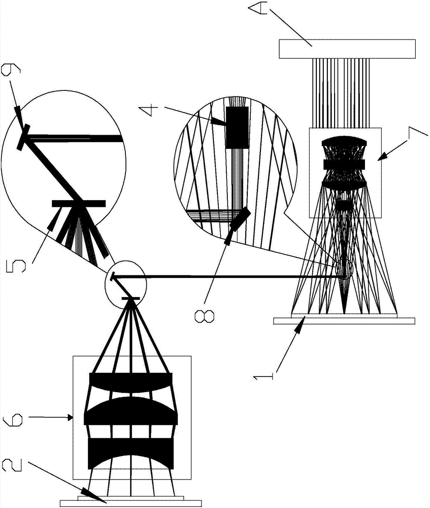
[0025] Embodiment one, such as figure 2 As shown, the imaging and light compression lens group is an imaging lens group 7, the imaging lens group 7 images the object A through the light reflected by the object A, and then projects the imaging light onto the image sensor 1 and simultaneously compresses part of the imaging light into a polychromatic light beam, the collimating lens group 4 is placed on the light-emitting side of the imaging lens group 7 and coaxially distributed with the imaging lens group 7 to collimate the polychromatic light beam into a polychromatic parallel light beam; and the total reflection mirror group includes the front The first stage total reflection mirror 8 and the rear stage total reflection mirror 9, the front stage total reflection mirror 8 is placed between the collimating lens group 4 and the image sensor 2 to form the polychromatic parallel beams formed after collimating through the collimating lens group 4 90° optical path steering, the rea...

Embodiment 2

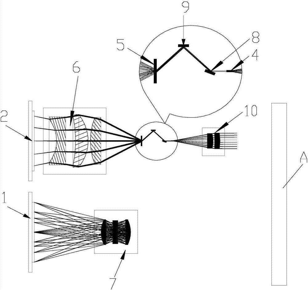
[0026] Embodiment two, such as image 3 As shown, the imaging and light compression lens group includes an imaging lens group 7 placed on the photosensitive surface side of the image sensor 1 and a light compression lens group 10 placed on the photosensitive surface side of the spectrum sensor 2 and distributed in parallel with the imaging lens group 7 (It is shared with imaging lens group 7), and imaging lens group 7 projects imaging light onto the image sensor 2 after imaging object A through the light reflected by object A, while light compression lens group 10 then reflects object A The light is compressed to form a polychromatic beam, and the collimating lens group 4 is placed on the light-emitting side of the light compression lens group 10 and distributed coaxially with the light compression lens group 10 to collimate the polychromatic beam into a polychromatic parallel beam; total reflection The mirror group includes a front-stage total reflection mirror 8 and a rear-s...


PUM


Abstract

The invention relates to the technical field of spectral analysis and provides a photographing type intelligent spectral analysis system. The photographing type intelligent spectral analysis system comprises a spectrum sensor, an image sensor, a collimating lens assembly, a total-reflection mirror assembly, a spectral separation lens and an imaging compression lens assembly, wherein the spectrum sensor and the image sensor are simultaneously arranged at a light exit side of an imaging and light compression lens assembly and are electrically connected with a system controller separately, the collimating lens assembly is arranged at the light exit side of the imaging and light compression lens assembly and is distributed coaxial with the imaging and light compression lens assembly, the total-reflection mirror assembly is arranged at a light exit side of the collimating lens assembly, the spectral separation lens is arranged at a light reflecting side of the total-reflection mirror assembly, and the imaging compression lens assembly is arranged between the spectral separation lens and a photosensitive surface of the spectrum sensor and is distributed coaxial with the spectral separation lens. According to the system provided by the invention, composition and content of substances of a target object can be accurately and rapidly analyzed while the target object is photographed; by using all the components in a matched manner, the sensitivity and detection accuracy of the system can be effectively improved, the directivity of the system is also effectively improved, and the detected object can be directed.

Description

technical field [0001] The invention relates to the technical field of spectrum analysis, and relates to a camera-type intelligent spectrum analysis system. Background technique [0002] Today, when the material conditions greatly meet the needs of modern life, people pay more and more attention to health. Due to the superior material conditions, people have more and more food to eat, and many lives that were never imagined before have been realized. In spite of this, people's health status has not been greatly improved, and various diseases (such as cancer) make many people with rich lives suffer from unprecedented pains and torments. The reason is mainly driven by factors such as the pursuit of high efficiency and high benefits, the amount of pesticide residues in the food we eat is too large, and our pharmaceutical processing environment has been polluted, resulting in a decline in drug efficacy and side effects. increase; most of our illnesses and pains are caused by e...

Claims


Application Information

Patent Timeline
IPC IPC(8): G01N21/25G01N21/84
CPCG01N21/25G01N21/84G01N2021/8466
Inventor 贺方建
Owner 深圳市帝泰光电有限公司
Why Eureka
Try Eureka