
Adjustment method of rotor position pi control parameters of permanent magnet synchronous motor

A permanent magnet synchronous motor and rotor position technology, applied in the direction of motor generator control, electronic commutation motor control, control system, etc., can solve the problem of difficult adjustment of PI controller parameters, achieve improved control performance, high accuracy, The effect of curbing blindness

Active Publication Date: 2019-07-02
JIAXING DEALOUR ELECTRIC TECH
View PDF10 Cites 0 Cited by
  • Summary
  • Abstract
  • Description
  • Claims
  • Application Information

AI Technical Summary

Problems solved by technology

[0005] Another purpose of the present invention is to solve the problem that the parameters of the PI controller are difficult to adjust according to the parameters of the controlled object when the closed-loop control of the rotor position of the permanent magnet synchronous motor adopts a PI controller, and propose a permanent magnet synchronous motor rotor position PI Adjustment method of control parameters

Method used


Image

  • Adjustment method of rotor position pi control parameters of permanent magnet synchronous motor
  • Adjustment method of rotor position pi control parameters of permanent magnet synchronous motor
  • Adjustment method of rotor position pi control parameters of permanent magnet synchronous motor

Examples


Embodiment Construction

[0050] The present invention will be further described in detail below in conjunction with the accompanying drawings, so that those skilled in the art can implement it with reference to the description.

[0051] It should be understood that terms such as "having", "comprising" and "including" as used herein do not entail the presence or addition of one or more other elements or combinations thereof.

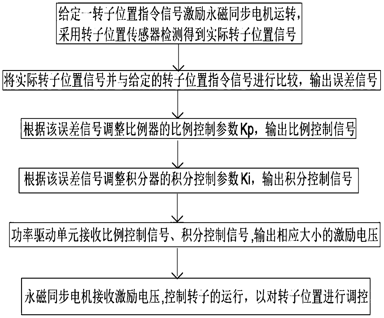
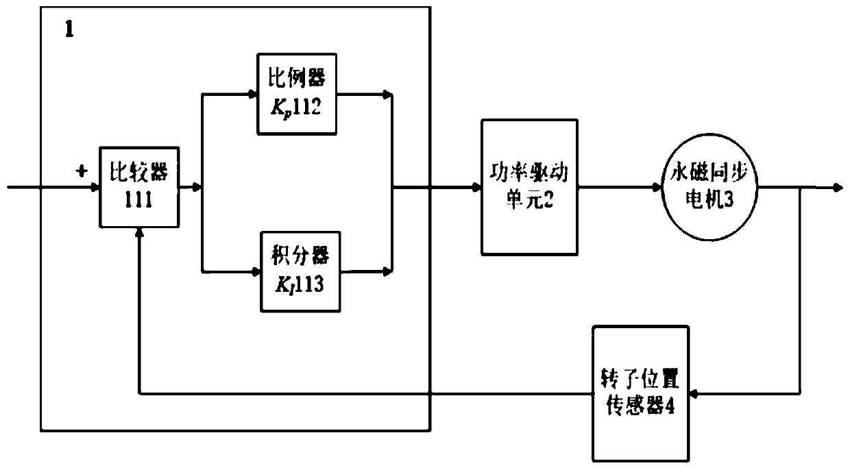
[0052] The invention provides a method for adjusting the PI control parameters of the rotor position of a permanent magnet synchronous motor, such as figure 1 As shown, the system used in this adjustment method includes: a controller 1, a power drive unit 2, a permanent magnet synchronous motor 3 and a rotor position sensor 4, wherein the controller 1 is composed of a comparator 111, a proportionalizer 112, and an integrator 113 , the first input terminal of the comparator 111 receives the rotor position command signal, the output terminal of the comparator 111 is respectively co...


PUM


Abstract

The present invention discloses a permanent magnet synchronous motor (PMSM) rotor position PI control parameters regulating method. A regulating system used in the regulating method comprises a controller, a power drive unit, a PMSM and a rotor position sensor. The controller consists of a comparator, a proportioner and an integrator. The regulating method comprises the following steps: the rotor position sensor detects an actual rotor position signal; the comparator receives the actual rotor position signal and a preset rotor position command signal and outputs an error signal; the proportioner and the integrator receive the error signal and output a proportional control signal and an integral control signal separately; the power drive unit receives each control signal and outputs an excitation voltage; the PMSM receives the excitation voltage and generates a rotor position. The regulating method has the advantages of scientification and feasibility, convenience for regulation, saving of time and manpower, high purposiveness and high accuracy. Furthermore, the regulating method can offer accurate basis for PMSM rotor position control designing and regulation, and thus good static performance and dynamic performance are realized.

Description

technical field [0001] The invention belongs to the field of permanent magnet synchronous motor control, and relates to a permanent magnet synchronous motor rotor position system and a control method. More specifically, the invention relates to a method for adjusting PI control parameters of the permanent magnet synchronous motor rotor position. Background technique [0002] The rotor position control of permanent magnet synchronous motor must adopt closed-loop control to obtain excellent rotor position control performance. Only by qualitatively understanding the controlled object can we decide what kind of controller to design, and only by quantitatively identifying the parameters of the controlled object can the controller The parameters are adjusted accurately. At present, the known controllers in the prior art, such as the widely used PI (proportional-integral) controller, do not firstly determine the parameters of the controlled object, but directly adjust the controlle...

Claims


Application Information

Patent Timeline
Patent Type & Authority Patents(China)
IPC IPC(8): H02P21/18
Inventor 张今朝朱海燕
Owner JIAXING DEALOUR ELECTRIC TECH
Learn More