
Double-layer LRM integrated air-cooled universal chassis

An integrated wind and chassis technology, which is applied in the direction of chassis/cabinet/drawer parts, cooling/ventilation/heating transformation, electrical components, etc., which can solve problems such as overheating of devices, large pressure loss of air ducts, and high heat flux density. , to reduce R&D and production processing costs, improve equipment reliability, maintain and replace the effect

Inactive Publication Date: 2017-08-01
10TH RES INST OF CETC
View PDF7 Cites 6 Cited by
  • Summary
  • Abstract
  • Description
  • Claims
  • Application Information

AI Technical Summary

Problems solved by technology

At present, for the development of aviation integrated electronic equipment, the outer dimensions of the chassis are customized according to the scale of the system module and the specific installation space of the equipment. The disadvantage of the existing technical scheme of the chassis is that the chassis cannot be directly transplanted and complies with GB / T3047 .2-1992 standard cabinet installation is not conducive to the rapid deployment of electronic systems
With the development of electronic technology, the increase of high-power electronic devices, and the current chassis basically adopt standard modules, the heat flux density is large, the heat dissipation space is small, and the heat generated in the unit volume is continuously increasing. The heat dissipation performance requirements of equipment are getting higher and higher, and device overheating has become one of the main reasons for the failure of electronic products, which seriously affects the reliability and working life of electronic equipment.
At present, if the electronic equipment chassis adopts module ventilation and cooling, if the number of modules is further increased, the width of the existing single-layer air-cooled chassis will be further increased. The anti-shock design brings difficulties; if double-layer installation is adopted, the commonly used overall solution of the chassis is to set the air source on the top or bottom of the chassis, and the cooling air enters from the bottom module and exits from the top module. Since the modules have various thickness series , the air ducts formed between the modules cannot be completely consistent, which will cause excessive pressure loss in the air ducts and affect the heat dissipation efficiency of the whole machine

Method used


Image

  • Double-layer LRM integrated air-cooled universal chassis
  • Double-layer LRM integrated air-cooled universal chassis
  • Double-layer LRM integrated air-cooled universal chassis

Examples


Embodiment Construction

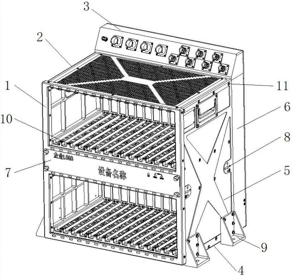
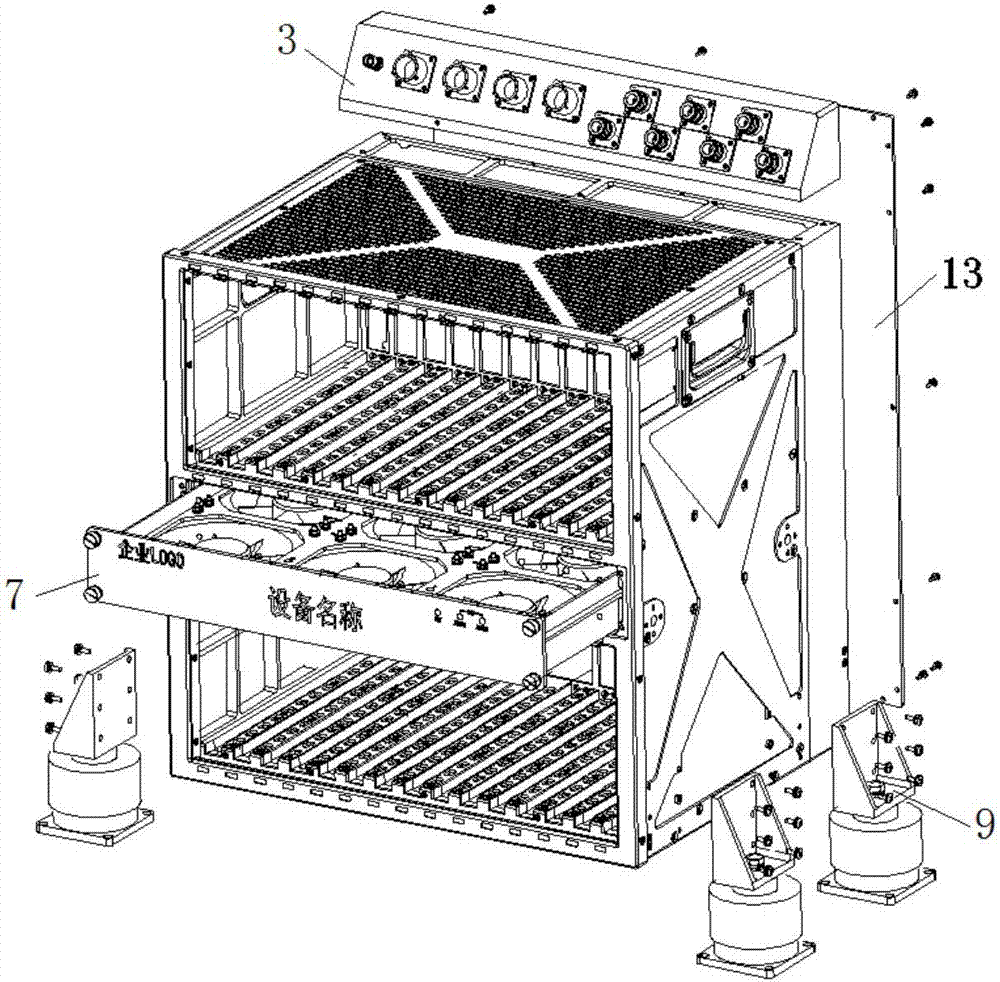
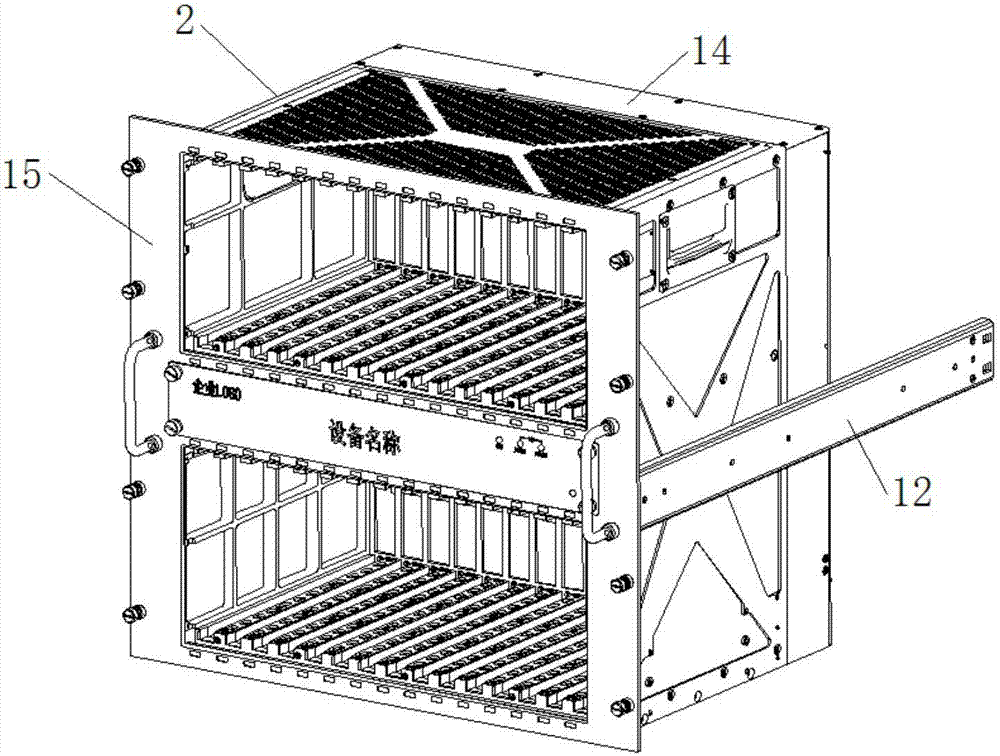
[0025] refer to Figure 1-Figure 2 . In the following example of a double-layer LRM integrated air-cooled universal chassis suitable for multiple platforms, a double-layer LRM integrated air-cooled universal chassis includes: the shape and interface of the chassis conform to GB / T3047.2-1992 The rectangular box frame adopts the overall structure of frame splicing. The rectangular box frame is surrounded by milled aluminum alloy structural parts of left side plate 1, right side plate 5, top plate 2, bottom plate 4 and back plate combination 6, and the left side plate 2. The right side panel 5, the top panel 2, the middle support panel 10, the bottom panel 4 and the back panel assembly 6 are fixedly connected to the rectangular box frame through the screw assembly 11, and the field-replaceable air source assembly module 7 is connected through the 4 on the panel. A captive screw is fixed to the frame. The inside of the chassis is filled with modules from left to right, and all m...


PUM


Abstract

The invention provides a double-layer LRM integrated air-cooled universal chassis. The air-cooled universal chassis is universal and modular, and is capable of improving the heat dissipation efficiency of the chassis. According to the technical scheme of the invention, an insertion slot and a support plate (10) of the insertion slot size series are arranged in the middle of a rectangular box body frame; a field replacement wind source component module (7) is arranged below the support plate; the wind source component module is located in the middle of a two-layer field replaceable module LRM module; two sets of fans which separately work and are arranged in a matrix are arranged in a wind source component module drawer box body; the fans provide air for a rack or through an environmental control air interface on the wind source component module; a micro-control unit MCU receives the fault signal of each set of fans; when the fans are used to provide air, cooling air come in from the bottom of the rack and come out from the top; and when environmental control air is used to provide air, cooling air come in from the environmental control air interface of a wind source component module panel and come out from the top and the bottom of the rack.

Description

technical field [0001] The invention relates to a general-purpose case mainly used for aviation and communication electronic equipment for integrating and installing field-replaceable modules LRM integrated electronic modules. Especially the dual-layer LRM integrated air-cooled general-purpose chassis for multiple installation platforms. Background technique [0002] With the rapid development of science and technology, electronic equipment has been widely used in various industries. Due to the harsh environmental conditions, electronic equipment is often subjected to various high temperatures, vibrations and shocks during work, which puts forward higher requirements for structural heat dissipation design. Among all electronic equipment, the operating environment of avionics can be said to be the most severe, and their operating environment temperature is usually -55 ~ +70 ℃. The cooling methods commonly used in domestic electronic equipment, such as air cooling, liquid coo...

Claims


Application Information

Patent Timeline
IPC IPC(8): H05K5/02H05K7/20
CPCH05K5/0247H05K7/20136
Inventor 冷献春
Owner 10TH RES INST OF CETC
Learn More