
Method for forming electrode patterns and electrode patterns

An electrode pattern and electrode technology, applied in the field of electrode patterns, can solve the problems of complex process and difficult formation of process characteristics, and achieve the effects of high design freedom, excellent position accuracy and quality improvement.

Inactive Publication Date: 2017-08-01
DONGJIN SEMICHEM CO LTD
View PDF5 Cites 8 Cited by
  • Summary
  • Abstract
  • Description
  • Claims
  • Application Information

AI Technical Summary

Problems solved by technology

However, since the method uses an electric field, it is limited by the need to use a conductive material with charging characteristics for the channel, so the process is complicated and it is difficult to form a thickness of more than 1 μm in terms of process characteristics.

Method used


Image

  • Method for forming electrode patterns and electrode patterns
  • Method for forming electrode patterns and electrode patterns
  • Method for forming electrode patterns and electrode patterns

Examples


Embodiment 1

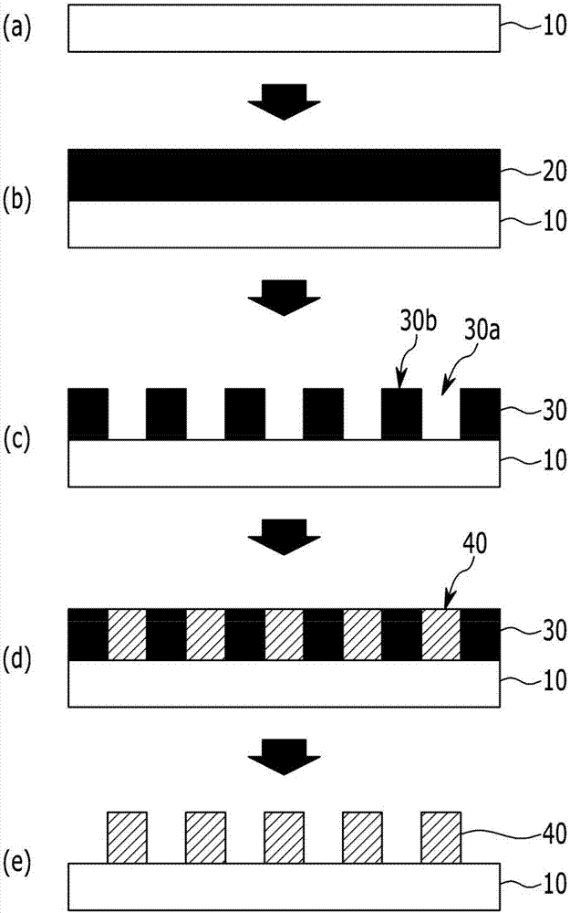
[0104] A soda-lime glass substrate generally used in the technical field to which the present invention pertains was prepared as a base for forming an electrode pattern.

[0105] The photoresist composition (DTFR-JC800, positive type, manufacturer: Dongjin Smicon) was coated on the substrate with a thickness of 6 μm by spin coating, and then the hot plate was used at 90 °C for 120 seconds. The thickness measured after prebaking was 3 μm.

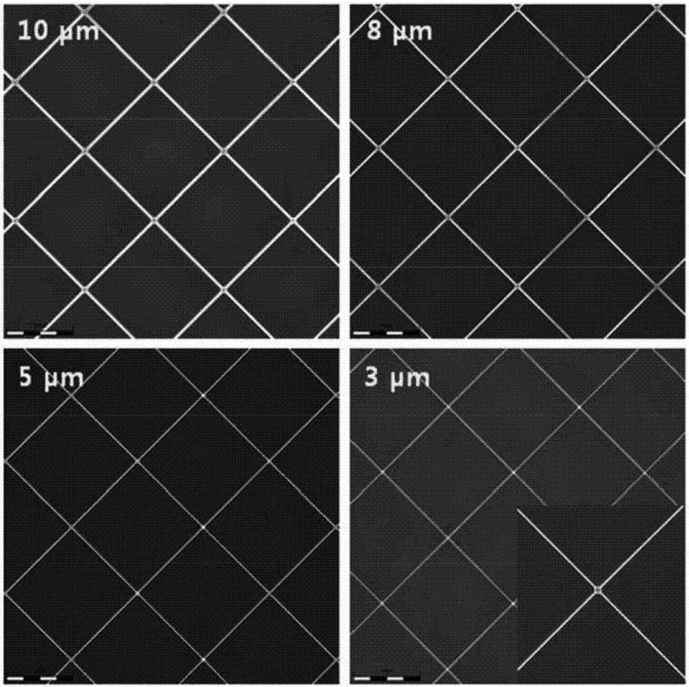
[0106] Then, the region coated with the photoresist composition was exposed to light with a wavelength of 365 nm by a proximity exposure machine (manufacturer: SEIWA) using a mask pattern for forming a line The mask pattern is a pattern with a width of 10 μm, and the cumulative exposure dose is 40 mJ.

[0107] Immerse the coated photoresist composition partially cured substrate in a developer solution (product name: DPD-200, alkaline developer solution, manufacturer: Dongjin Smicon) at 25°C for 60 seconds Development is performed to form ...

Embodiment 2

[0112] An electrode pattern was formed by the same method as in Example 1 except that the line width was 8 μm.

Embodiment 3

[0114] An electrode pattern was formed by the same method as in Example 1 except that the line width was 5 μm.


PUM

PropertyMeasurementUnit
widthaaaaaaaaaa
widthaaaaaaaaaa

Abstract

The present invention relates to a method for forming electrode patterns. The method for forming the electrode patterns of the present invention is applicable to various devices which require microelectrode patterning and, particularly, is useful to be applicable to forming a touch sensor provided in a touch screen panel (TSP).

Description

technical field [0001] The invention relates to a method for forming an electrode pattern and the electrode pattern. More specifically, the present invention relates to a method for forming an electrode pattern with a small line width and an electrode pattern that can be used to form a touch sensor included in a touch screen panel (TSP). Background technique [0002] The touch screen panel inputs information corresponding to the screen by pressing the screen displayed on the panel. Because of the convenience in use, touch screen panels are increasingly applied to all display devices recently. [0003] Generally, the touch panel extracts the coordinates of the pressed portion by a capacitive method, a resistive method, a surface ultrasonic method, an infrared method, etc., and inputs information. In the capacitive method, when the user touches the screen, the capacitance of the human body is used to identify the amount of current change and detect the position. [0004] Th...

Claims


Application Information

Patent Timeline
Patent Type & Authority Applications(China)
IPC IPC(8): G06F3/044H01B5/14H01B13/00G03F7/00
CPCG03F7/00G06F3/044G06F2203/04111H01B5/14H01B13/00G06F3/041
Inventor 金浩钟郑泽晟韩辰基李升爀
Owner DONGJIN SEMICHEM CO LTD
Learn More