Steel bar integrated binding mold of prefabricated box girder and use method of steel bar integrated binding mold

A kind of steel bar and integral technology, which is applied in the field of prefabricated box girder steel bar integral binding mold, can solve the problems of unfavorable land saving, high steel bar skeleton, low work efficiency, etc., and achieve the effect of reducing the occupied area, reducing the amount of welding, and reducing the amount of materials used

Inactive Publication Date: 2017-08-04
CHINA COMM 2ND NAVIGATIONAL BUREAU 2ND ENG
View PDF4 Cites 7 Cited by
  • Summary
  • Abstract
  • Description
  • Claims
  • Application Information

AI Technical Summary

Problems solved by technology

This method has the following disadvantages: 1) The steel skeleton is relatively high, and scaffolding needs to be set up in the outer mold as an operating platform, but it must be removed when installing the inner mold, and the work efficiency is extremely low
2) There is no positioning device in the formwork, the spacing of various steel bars is not easy to ensure, and the spatial positioning of prestressed pipes cannot be accurately completed
3) The binding operation of the chamfered connecting bars between the bottom web steel bars and the top plate steel bars is very difficult (the operator needs to climb on the top plate steel bars to fix the chamfered connecting bars), the integrity of the steel bar skeleton is poor, and the quality is difficult to guarantee
4) The synchronous construction of steel bar binding process and formwork cleaning and polishing cannot be realized, and the garbage generated in the process of steel bar binding is difficult to clean up, which not only has low work efficiency but also seriously affects the internal quality of prefabricated products
This method has the following disadvantages: 1) The fixed bottom web steel bar binding mold and the top plate steel bar binding mold are processed separately, and the number is 1:1
Compared with the overall mold, it occupies twice the area, which is unfavorable for the space
2) The amount of section steel used to process the bottom web steel frame and roof steel frame is twice that of the overall steel bar binding mold, which is not conducive to material saving
3) In separate binding, the steel frame of each box girder needs to be hoisted twice, while in the case of integral binding, the steel frame of each box girder only needs to be hoisted once, and the work efficiency of split binding of the steel frame is also low
4) Same as the direct binding in the formwork, the binding operation of the chamfered connecting bars between the bottom web steel bars and the top plate steel bars is very difficult (the operator needs to climb on the top plate steel bars to fix the chamfered connecting bars), the integrity of the steel frame is poor, and the quality hard to guarantee
[0006] In the prior art, the technology of tying the steel bars of prefabricated box girders on the overall mold is not yet mature, and there are many problems in structural design and manufacturing, such as inconvenient use, low efficiency, low safety, etc.

Method used


Image

  • Steel bar integrated binding mold of prefabricated box girder and use method of steel bar integrated binding mold
  • Steel bar integrated binding mold of prefabricated box girder and use method of steel bar integrated binding mold
  • Steel bar integrated binding mold of prefabricated box girder and use method of steel bar integrated binding mold

Examples


Embodiment Construction

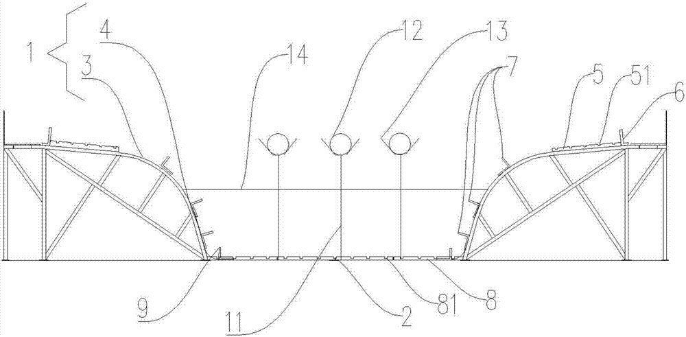
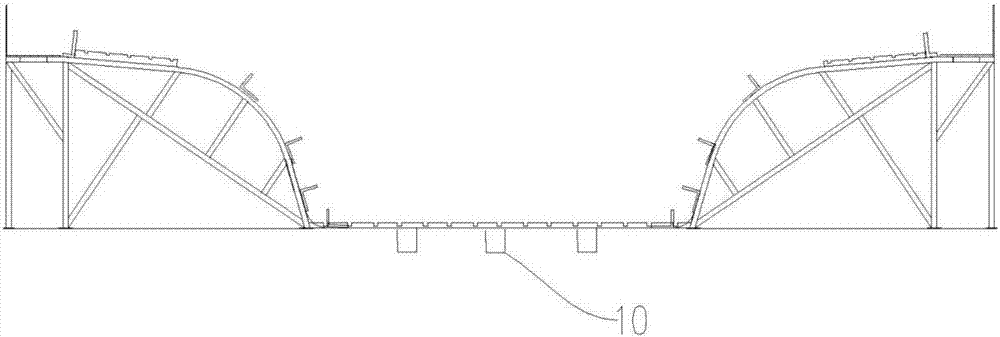
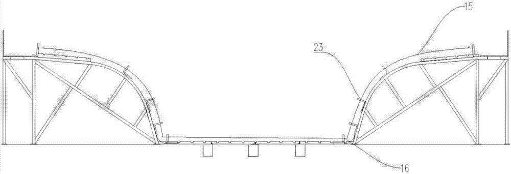
[0040] The present invention will be further described in detail below in conjunction with the accompanying drawings, so that those skilled in the art can implement it with reference to the description.

[0041] It should be understood that terms such as "having", "comprising" and "including" as used herein do not entail the presence or addition of one or more other elements or combinations thereof. In the description of the present invention, the terms "transverse", "longitudinal", "axial", "radial", "upper", "lower", "front", "rear", "left", "right", The orientations or positional relationships indicated by "vertical", "horizontal", "top", "bottom", "inner", "outer", etc. are based on the orientation or positional relationships shown in the drawings, and are only for the convenience of describing the present invention and simplified descriptions, do not indicate or imply that the device or element referred to must have a specific orientation, be constructed and operate in a ...


PUM

PropertyMeasurementUnit
lengthaaaaaaaaaa

Abstract

The invention discloses a steel bar integrated binding mold of a prefabricated box girder and a use method of the steel bar integrated binding mold. The steel bar integrated binding mold of the prefabricated box girder comprises an outer mold frame and an inner mold frame, wherein the outer mold frame comprises two side formworks and a bottom formwork, the side formworks include an upper side formwork and a lower side formwork which are integrally formed, the upper side formwork is provided with a plurality of first plate bodies at intervals in the longitudinal direction, the upper side formwork is provided with at least one second plate body, the lower side formwork is provided with a plurality of third plate bodies at intervals from bottom to top, the bottom formwork is provided with a plurality of fourth plate bodies at intervals in the longitudinal direction, and the two ends, in the transverse direction, of the bottom formwork are each provided with at least one fifth plate body; and the inner mold frame comprises a plurality of lines of top plate steel bar binding supporting sleeves, a plurality of top plate longitudinal shaping steel pipe supporting pipes and a plurality of top plate longitudinal shaping steel pipes all of which are arranged at intervals in the transverse direction. The steel bar integrated binding mold of the prefabricated box girder is small in investment in use, low in cost, high in adaptive capacity, easy to construct, rapid and high in safety.

Description

technical field [0001] The invention relates to a steel bar binding tire. More specifically, the present invention relates to a prefabricated box girder steel bar integral binding mold and its application method. Background technique [0002] Large-scale prefabricated box girders are prestressed reinforced concrete components. There are many types of steel bars, all kinds of steel bars cross vertically and horizontally, and the error of steel bar spacing is small. Higher and more difficult, in order to realize the tying and forming of the prefabricated box girder steel skeleton, the following three methods are generally adopted. [0003] One is to bind directly in the formwork, instead of binding and forming on the steel bar binding mold, first bind the bottom web steel skeleton in the formwork on the pedestal, then install the inner mold, then bind the top plate steel skeleton on the formwork, and finally bind the inverted Angle connecting steel bars into a whole. This m...

Claims


Application Information

Patent Timeline
Patent Type & Authority Applications(China)
IPC IPC(8): B28B23/04
CPCB28B23/043
Inventor 何志军郭万中幸元野史明胜罗益俊
Owner CHINA COMM 2ND NAVIGATIONAL BUREAU 2ND ENG
Why Eureka
Try Eureka