Invisible reinforcing device for concrete cantilever gallery road and reinforcing method thereof

A reinforcement device and concrete technology, applied in bridge reinforcement, bridge erection/assembly, bridge maintenance, etc., can solve problems such as high requirements for construction environment and construction level, high requirements for shear strength of superimposed surfaces, and unsuitable for scenic plank roads. , to achieve significant environmental protection, reduce construction costs, and improve construction efficiency.

Inactive Publication Date: 2017-08-04
HENAN UNIV OF SCI & TECH
View PDF6 Cites 3 Cited by
  • Summary
  • Abstract
  • Description
  • Claims
  • Application Information

AI Technical Summary

Problems solved by technology

If the cross-section is enlarged and the bending steel bars are added in the upper part, it will encounter the problem that the old and new parts of the laminated member work together, and the requirements for the shear strength of the laminated surface are relatively high; The problem of hysteresis, because the steel plate cannot bear the existing load, but only bears the newly added load in the future; the method of sticking carbon fiber reinforcement has high requirements on the construction environment and construction level, and is not suitable for the reinforcement of the plank road in scenic spots; the external prestressing currently used The reinforcement method refers to the post-tensioning method that generates prestress by tensioning the steel strands arranged outside the main body of the load-bearing structure. It is composed of steel strands, external prestressed hole tubes, slurry, anchoring systems and steering blocks. The method is complicated, and the equipment required is large and professional, and it is not suitable for the small components of the narrow site of the plank road in the scenic spot, especially the reinforcement of the concrete cantilever plank road in the scenic spot with protection value

Method used


Image

  • Invisible reinforcing device for concrete cantilever gallery road and reinforcing method thereof
  • Invisible reinforcing device for concrete cantilever gallery road and reinforcing method thereof
  • Invisible reinforcing device for concrete cantilever gallery road and reinforcing method thereof

Examples


Embodiment Construction

[0029] In order to facilitate the understanding of the technical means, creative features and goals achieved by the present invention, the present invention is further described below in conjunction with the schematic diagrams, but the scope of protection claimed by the present invention is not limited to the scope described in the specific implementation.

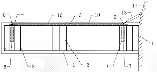
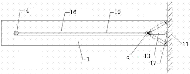
[0030] An invisible reinforcement device for concrete cantilever planks, such as figure 1 As shown, the device comprises a concrete cantilever member 1, one end of the concrete cantilever member 1 is a cantilever end fixedly connected to the rock wall 11, the other end of the concrete cantilever member 1 is a free end, and the concrete cantilever member 1 is provided with a vertical hoop The ribs 2 and the stressed steel bars 3 arranged laterally extending from the cantilever end to the free end, the stirrups 2 are densely distributed in multiples.

[0031] Among them, the free end of the concrete cantilever member 1 is pr...


PUM


Abstract

The invention provides an invisible reinforcing device for concrete cantilever gallery road and a reinforcing method thereof. The device comprises a concrete cantilever component and a long reinforcing steel bar, wherein stirrups and tensile bars are arranged in the concrete cantilever component; the free end of the concrete cantilever component is provided with a blind hole I which is longitudinally formed; a reinforcing steel bar I is fixedly arranged in the blind hole I; a round ring I is fixedly arranged at the end, extending out of the blind hole I, of the reinforcing steel bar I; a blind hole II is longitudinally formed in the cantilever end of the concrete cantilever component, and a reinforcing steel bar II is fixedly arranged in the blind hole II; a round ring II is arranged at the end, extending out of the blind hole II, of the reinforcing steel bar II, and can rotate around the axis of the reinforcing steel bar II at 360 degrees; one end of the long reinforcing steel bar is fixedly connected with the round ring I, and the other end of the long reinforcing steel bar runs through the round ring II and is fixedly arranged on a rock wall; and a strain gauge is adhered to the long reinforcing steel bar between the rock wall and the round ring II. According to the reinforcing method, prestress is applied to a component to improve the safety of the component; and construction under the component can be avoided, and scaffold construction is not required.

Description

technical field [0001] The invention relates to the technical field of construction engineering reinforcement, in particular to the reinforcement of structural components, in particular to an invisible reinforcement device for a concrete cantilever plank and a reinforcement method thereof. Background technique [0002] At present, the plank roads in most scenic spots use reinforced concrete cantilever components. If the reinforced concrete cantilever components are old, the concrete protective layer will be damaged, the concrete will be carbonized, and the steel bars will be corroded, resulting in a reduction in the bearing capacity and reliability of the concrete components. [0003] At present, for the reinforcement of cantilever members, there are methods of enlarging the concrete section, pasting the steel plate to enlarge the section, pasting the carbon fiber cloth, external prestressed reinforcement, etc. If the cross-section is enlarged and the bending steel bars are ...

Claims


Application Information

Patent Timeline
Patent Type & Authority Applications(China)
IPC IPC(8): E01D18/00E01D22/00
CPCE01D18/00E01D22/00
Inventor 高笑娟李跃辉马建军李达聂梦强赵林
Owner HENAN UNIV OF SCI & TECH
Why Eureka
Try Eureka