Tamping machine with dedusting device
A technology of dust removal device and tamping machine, which is applied in the field of construction machinery, can solve problems such as high dust content and reduced working environment, and achieve the effects of optimizing the working environment, prolonging life, and improving comfort
- Summary
- Abstract
- Description
- Claims
- Application Information
AI Technical Summary
Problems solved by technology
Method used
Image

Examples
Embodiment 1
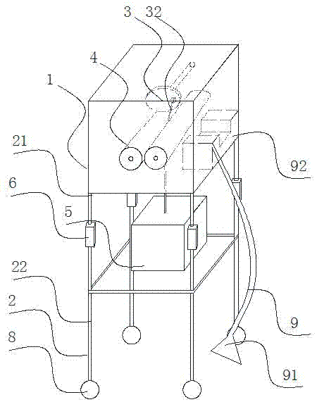
[0025] This implementation provides a tamping machine with a dust removal device, such as Figure 1-2 As shown, it includes a work box 1, a support 2 supporting the work box 1 and a dust suction device 9, wherein,
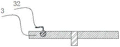
[0026] The working box 1 is provided with a runner 3 that rotates on a vertical plane. Below the runner 3, there are two driven rollers 4 that are parallel to each other and located on the same plane. The runner 3 is close to the edge A connection chain 32 is movably connected, and the connection chain 32 passes through the gap between the two driven rollers 4 and the bottom surface of the work box 1 in turn, and is connected with the lifting box 5 below the work box 1;
[0027] The dust collector 9 includes a water tank 92 and an exhaust fan. The water tank 92 is U-shaped, and one end is closed and the other end is open. one end;
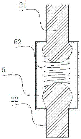
[0028] Described support 2 comprises more than three vertical rods, and described vertical rod comprises upper rod 21, lower rod 22 ...
Embodiment 2
[0033] This embodiment is based on the embodiment 1, and is further defined: the rotating shafts of the two driven rollers 4 are parallel to the rotating shaft of the runner 3, and the surface of the driven rollers 4 is provided with a limiting groove at the place where the connecting chain 32 fits. Prevent the connecting chain 32 from sliding to both ends along the surface of the driven drum 4, which will affect the tamping.
Embodiment 3
[0035] This embodiment is based on the embodiment 1, and further defines that: the air outlet 91 of the exhaust fan is set above the liquid level of the water tank 92 . To prevent the suction generated after the fan stops working.
PUM
 Abstract
Description
Claims
Application Information
 - Generate Ideas
- Intellectual Property
- Life Sciences
- Materials
- Tech Scout
- Unparalleled Data Quality
- Higher Quality Content
- 60% Fewer Hallucinations
Browse by: Latest US Patents, China's latest patents, Technical Efficacy Thesaurus, Application Domain, Technology Topic, Popular Technical Reports.
© 2025 PatSnap. All rights reserved.Legal|Privacy policy|Modern Slavery Act Transparency Statement|Sitemap|About US| Contact US: help@patsnap.com