Check patentability & draft patents in minutes with Patsnap Eureka AI!

An optical fiber temperature sensing device

A sensing device and optical fiber temperature technology, applied in thermometers, measuring devices, thermometers with physical/chemical changes, etc., can solve the problems of anti-interference and simple demodulation methods, and the inability of optical fiber sensors to take into account high sensitivity, etc., to achieve increased Dynamic measurement range, added practical value, effect of low phase noise

Active Publication Date: 2019-05-14
HUAZHONG UNIV OF SCI & TECH
View PDF5 Cites 0 Cited by
  • Summary
  • Abstract
  • Description
  • Claims
  • Application Information

AI Technical Summary

Problems solved by technology

[0005] In view of the above defects, the object of the present invention is to provide an optical fiber temperature sensing device, which aims to solve the technical problem that the optical fiber sensor cannot take into account high sensitivity, anti-interference and simple demodulation method due to the structure of the optical fiber sensor in the prior art

Method used


Image

  • An optical fiber temperature sensing device
  • An optical fiber temperature sensing device
  • An optical fiber temperature sensing device

Examples


Embodiment Construction

[0040] In order to make the object, technical solution and advantages of the present invention clearer, the present invention will be further described in detail below in conjunction with the accompanying drawings and embodiments. It should be understood that the specific embodiments described here are only used to explain the present invention, not to limit the present invention.

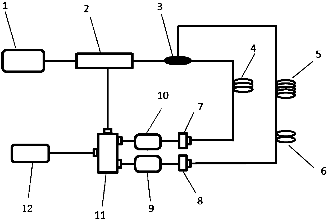
[0041] figure 1 The schematic diagram of the structure of the optical fiber temperature sensing device provided by the present invention, the optical fiber temperature sensing device includes a photoelectric modulation unit 2 and a beam splitting unit 3, the input end of the photoelectric modulation unit 2 is used to connect with the output end of the laser generating unit 1, and the photoelectric modulation unit 2 is used to connect with the output end of the laser generating unit 1. The modulating unit 2 is used for modulating the laser signal output by the laser generating unit 1 according to th...


PUM


Abstract

The invention discloses an optical fiber temperature sensing device, which comprises a photoelectric modulation unit, a beam splitting unit, a first branch, a second branch and a combining unit. The beam unit constitutes the first oscillating circuit, the first oscillating circuit is used to realize the oscillation of the first microwave signal, the second oscillating circuit is composed of the photoelectric modulation unit, the beam splitting unit, the second branch and the beam combining unit, In order to realize the oscillation of the second microwave signal, the resonant wave is obtained by superimposing the first microwave signal and the second microwave signal. When the temperature signal is loaded into the sensing area of ​​the second optical fiber, the oscillation peak of the resonant wave drifts. Obtaining the intensity variation of the resonant wave at a fixed frequency can realize the demodulation of the temperature signal. The device provided by the invention has high sensitivity, strong anti-interference ability, small phase noise, wide measurement range and simple demodulation, and can be used for optical fiber communication.

Description

technical field [0001] The invention belongs to the technical field of optical fiber sensing, and more specifically relates to an optical fiber temperature sensing. technical background [0002] The development of optical fiber sensing technology began in the 1970s, and it is one of the most active branches of optoelectronic technology. Because the optical fiber has many characteristics such as high sensitivity, anti-electromagnetic interference, small size, and easy formation of arrays. Therefore, the optical fiber sensing technology has received great attention since it came out, and has been researched and applied in almost every field. It has become the forerunner of sensing technology and promoted the vigorous development of sensing technology. [0003] Compared with traditional sensors, the use of optical fibers for sensing has many advantages: optical fibers are small in size and light in weight, and are easy to embed in the structure to be tested; they have good ins...

Claims


Application Information

Patent Timeline
Patent Type & Authority Patents(China)
IPC IPC(8): G01K11/32G01K11/3206
CPCG01K11/32
Inventor 夏历刘康
Owner HUAZHONG UNIV OF SCI & TECH
Features
  • R&D
  • Intellectual Property
  • Life Sciences
  • Materials
  • Tech Scout
  • Unparalleled Data Quality
  • Higher Quality Content
  • 60% Fewer Hallucinations
Learn More