Particle flow simulation method

A simulation method and particle technology, applied in design optimization/simulation, resource allocation, program control design, etc., can solve the problems of insufficient CPU computing power, high construction cost, high use and maintenance cost, and reduce the overlap area and communication. The effect of improving computing efficiency and reducing energy consumption

Inactive Publication Date: 2017-08-04
CHINA UNIV OF PETROLEUM (BEIJING)
View PDF3 Cites 9 Cited by
  • Summary
  • Abstract
  • Description
  • Claims
  • Application Information

AI Technical Summary

Problems solved by technology

At present, the implementation of DEM methods is mainly based on CPU. Due to the insufficient computing power of CPU, these methods can only calculate small spatial and temporal dimensions within an acceptable computer time; or due to high construction costs, it is necessary to build Large-scale or even ultra-large-scale CPU computer clusters consume too much power, and the cost of use and maintenance is extremely high
In addition, the current DEM method implemented by CPU either has a small number of particles or a low-density particle collision, which cannot fully realize the high-density and large-scale particle collision simulation

Method used


Image

  • Particle flow simulation method
  • Particle flow simulation method
  • Particle flow simulation method

Examples


Embodiment Construction

[0071] The preferred embodiments of the present invention will be described below in conjunction with the accompanying drawings. It should be understood that the preferred embodiments described here are only used to illustrate and explain the present invention, and are not intended to limit the present invention.

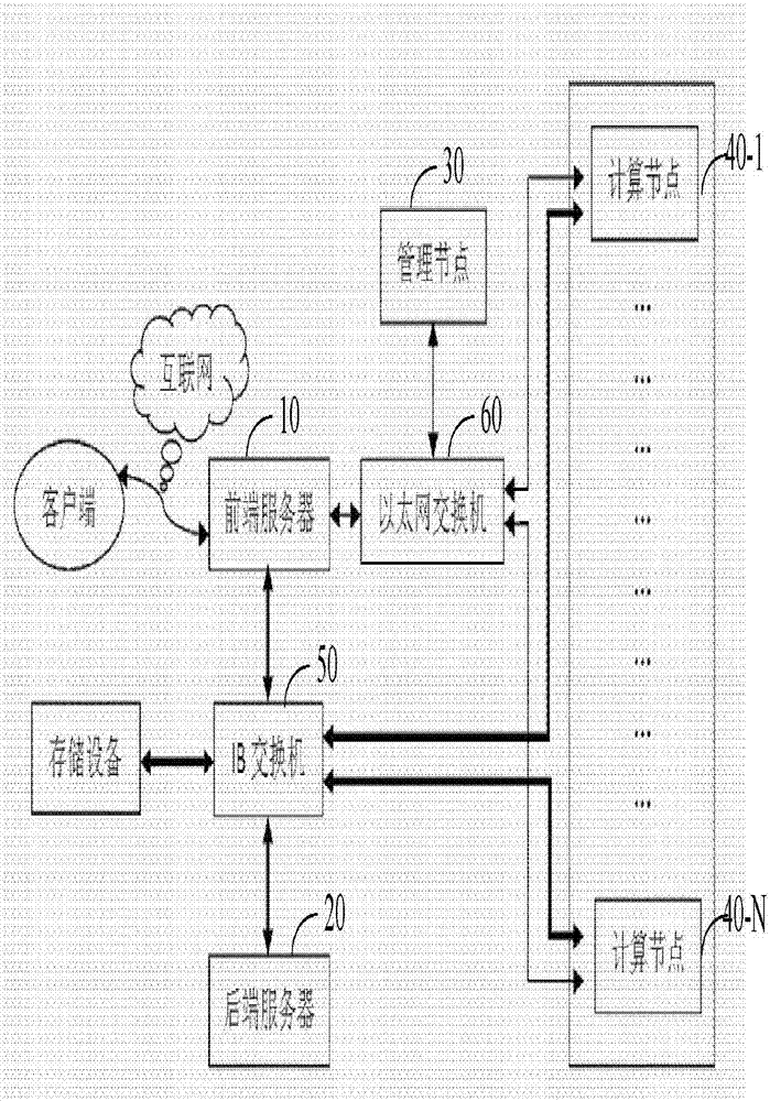
[0072] figure 1 is a structural schematic diagram of a particle flow simulation method according to an embodiment of the present invention. Such as figure 1 As shown, the system includes a front-end server 10, a back-end server 20, a management node 30, a plurality of computing nodes 40-1, . . . , 40N (N is an integer greater than 1), an IB switch 50 and an Ethernet switch 60. also, figure 1 It is also shown that the system includes a client and a storage device. The client can communicate with the front-end server 10 via the Internet, which enables field experimenters to conduct particle flow simulation experiments remotely. For example, the user can input the ...


PUM


Abstract

The invention discloses a particle flow simulation method. The particle flow simulation method includes the steps that particle information is generated according to particle modeling information input by a client side, and geometry information is generated; the particle information and the geometry information are received, which GPU in which calculation nodes are determined to be used according to the number of particles and the number of unoccupied GPU in all the calculation nodes, then which particles calculated by which GPU of which node are determined according to the determined number of the GPU and the distribution condition of the particles in the space, and distribution is carried out according to the determined result; stress, caused by particle impact, on each particle is calculated in multiple GPU in parallel, then accelerated speed is calculated to simulate particle flow; the simulation result is displayed. According to the embodiment, high-density particle virtual experiment simulation can be achieved, computation efficiency is improved while energy consumption is reduced.

Description

technical field [0001] The invention relates to the technical field of particle flow simulation, in particular to a particle flow simulation method. Background technique [0002] Particle system has always been the research content of people's attention. In industrial fields such as: food control, chemistry, civil engineering, oil and gas, mining, pharmaceuticals, powder metallurgy, energy and other fields have a large number of applications; in terms of theoretical research, how to accumulate the most dense accumulation, and under what circumstances the sand pile collapses To study issues such as avalanches. In order to study related particle systems, people need to build large-scale experimental particle systems, which is time-consuming and labor-intensive. Moreover, due to the high cost, some particle systems need to operate under extreme conditions, so it is impossible to build them through experiments, while the simulation system based on virtual experiments does not ...

Claims


Application Information

Patent Timeline
Patent Type & Authority Applications(China)
IPC IPC(8): G06F17/50G06F9/50
CPCG06F9/505G06F30/20Y02D10/00
Inventor 杨晨周福建高李阳冯炜
Owner CHINA UNIV OF PETROLEUM (BEIJING)
Why Eureka
Try Eureka