Imaging quality simulation method of Fresnel diffraction optical system
A technology of Fresnel diffraction and optical system, which is applied in the field of imaging quality simulation of Fresnel diffraction optical system, to achieve the effect of low MTF, low SNR, and low contrast
- Summary
- Abstract
- Description
- Claims
- Application Information
AI Technical Summary
Problems solved by technology
Method used
Image

Examples
specific Embodiment approach 1
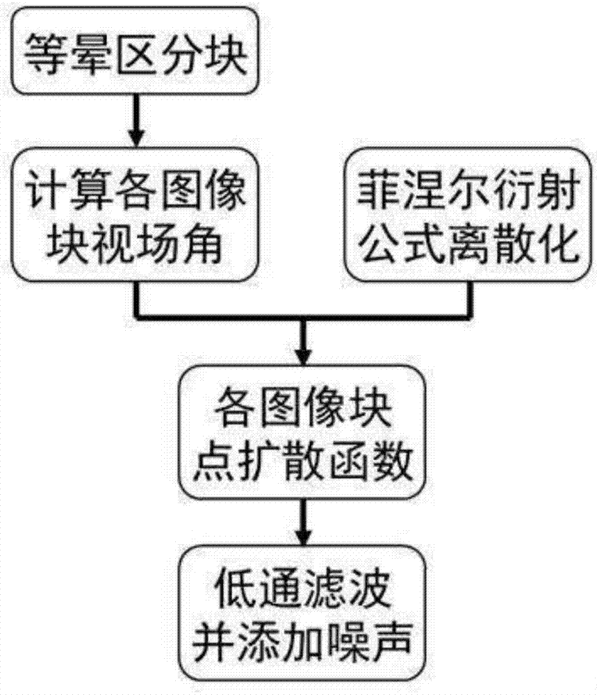
[0030] Specific implementation mode one: as figure 1 As shown, what is described in this embodiment is a method for simulating the imaging quality of a Fresnel diffractive optical system, and the steps of the method are as follows:
[0031] Step 1: Based on the idea of equal halo area blocks, the original image is divided into several image blocks with approximately the same point spread function;
[0032] Step 2: Calculate the position of the meridian plane at the center of each image block and its corresponding field of view;
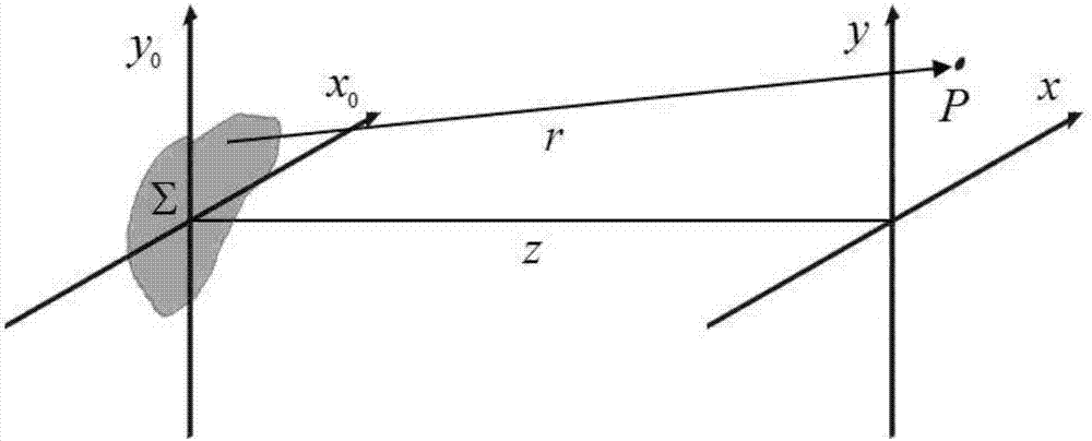
[0033] Step 3: Construct a discretized Fresnel diffraction formula, and calculate the point spread function of each image block;
[0034] Step 4: Low-pass filtering is performed on each image block by using the MTF of different regions of the image, and random noise is added.
specific Embodiment approach 2
[0035] Specific implementation mode two: as figure 1 As shown, the imaging quality simulation method of a Fresnel diffractive optical system described in the first embodiment, the specific steps of the first step are as follows:
[0036] (1) Based on the block idea of equal halo area, the original image is divided into several image blocks with approximately the same point spread function:
[0037] The Fresnel diffraction imaging system has obvious PSF spatial shift characteristics, and its degradation model can be expressed as:
[0038] Y=H(ω x , ω y )X+Noi
[0039] In the formula, Y is the degraded image spectrum; H(ω x , ω y ) means the field of view is (ω x , ω y ), the optical system transfer function (MTF); Noi is the noise spectrum; X represents the original image spectrum;
[0040] (2) Design overlapping regions between adjacent image blocks of several image blocks with approximately the same point spread function; take the center of the image as the origin, ...
specific Embodiment approach 3
[0041] Specific implementation mode three: as figure 1 As shown, the imaging quality simulation method of a Fresnel diffractive optical system described in the second embodiment, the specific steps of the second step are as follows:
[0042] (1) Calculate the field angle of each image block in the x-axis and y-axis directions:
[0043] Let the focal length of the diffractive optical imaging system be f, and the pixel size be P 1 , then the center coordinates are (x a ,y b ) image block in x, y direction field angle ω x and ω y They are:
[0044]
[0045]
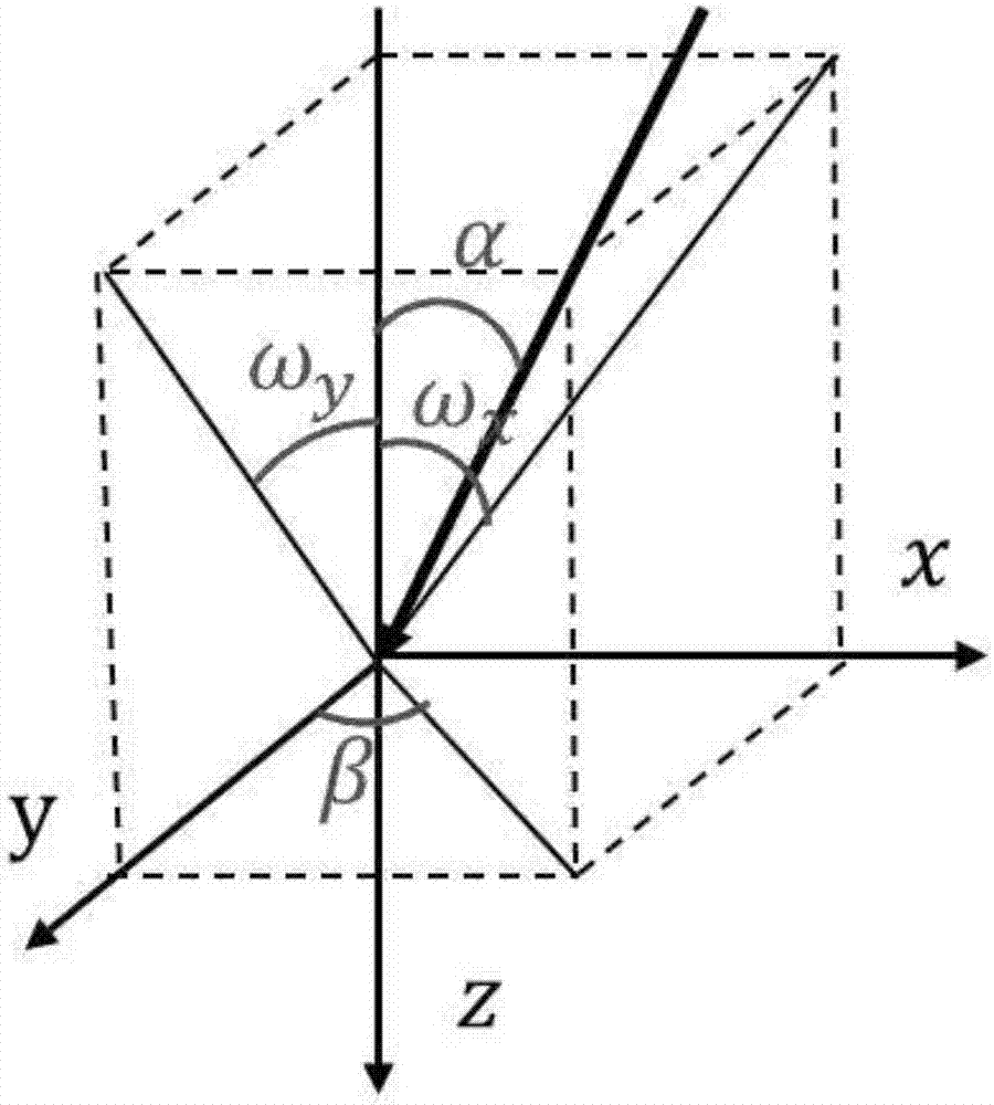
[0046] (2) Calculate the field angle of each image block on the meridian plane:
[0047] Such as figure 2 As shown, from the spatial geometric relationship, it can be known that the angle of view α on the meridian plane and the angle β between the meridian plane and the y-axis are:
[0048]
[0049]
[0050] In the formula, sign( ) is a sign function.
PUM
 Abstract
Description
Claims
Application Information
 - R&D
- Intellectual Property
- Life Sciences
- Materials
- Tech Scout
- Unparalleled Data Quality
- Higher Quality Content
- 60% Fewer Hallucinations
Browse by: Latest US Patents, China's latest patents, Technical Efficacy Thesaurus, Application Domain, Technology Topic, Popular Technical Reports.
© 2025 PatSnap. All rights reserved.Legal|Privacy policy|Modern Slavery Act Transparency Statement|Sitemap|About US| Contact US: help@patsnap.com