Radio frequency transmitting and receiving circuit

A technology of radio frequency reception and radio frequency transmission, which is applied in the field of communication, can solve the problem of low performance and achieve the effect of reducing loss, low loss and reducing complexity

Active Publication Date: 2017-08-04
WEARLINKS TECH INC
View PDF4 Cites 14 Cited by
  • Summary
  • Abstract
  • Description
  • Claims
  • Application Information

AI Technical Summary

Problems solved by technology

The switch selection circuit will introduce additional loss in the signal path, causing the performance of the product application to be lower than its original design specification

Method used


Image

  • Radio frequency transmitting and receiving circuit
  • Radio frequency transmitting and receiving circuit
  • Radio frequency transmitting and receiving circuit

Examples


Embodiment Construction

[0030] The present invention will be further described in detail below in conjunction with the accompanying drawings and embodiments. It should be understood that the specific embodiments described here are only used to explain the present invention, but not to limit the present invention. In addition, it should be noted that, for the convenience of description, only some structures related to the present invention are shown in the drawings but not all structures.

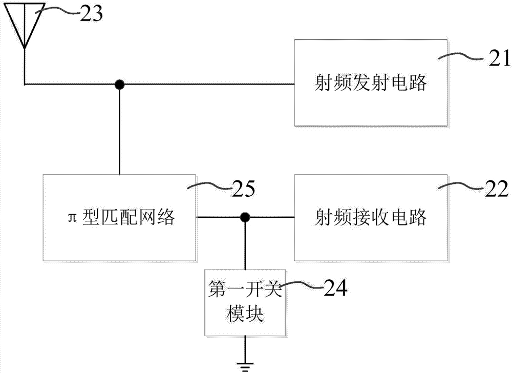
[0031] Figure 2A It is a circuit diagram of a radio frequency transceiver circuit provided by an embodiment of the present invention. see Figure 2A , the radio frequency transceiver circuit includes:

[0032] A radio frequency transmitting circuit 21, the output end of the radio frequency transmitting circuit 21 is electrically connected to the antenna 23;

[0033] The radio frequency receiving circuit 22, the first input end of the radio frequency receiving circuit 22 is grounded through the first switch mod...


PUM


Abstract

The embodiment of the invention discloses a radio frequency transmitting and receiving circuit. The circuit comprises a radio frequency transmitting circuit, wherein the output end of the radio frequency transmitting circuit is electrically connected with an antenna; a radio frequency receiving circuit, wherein the first input end of the radio frequency receiving circuit is grounded through a first switching module; and a TT-type matching circuit, wherein the first input end of the radio frequency receiving circuit is electrically connected with the antenna through the TT-type matching circuit. The first switching module is switched on when the radio frequency transmitting circuit works and is switched off when the radio frequency receiving circuit works. According to the technical scheme provided by the embodiment of the invention, on the basis of effectively isolating the radio frequency receiving circuit and the radio frequency transmitting circuit, the power consumption and cost of the radio frequency transmitting and receiving circuit are reduced, and the performance of the radio frequency transmitting and receiving circuit is optimized.

Description

technical field [0001] Embodiments of the present invention relate to communication technologies, and in particular to a radio frequency transceiver circuit. Background technique [0002] In the radio frequency circuit system, in order to make the radio frequency receiver and the radio frequency transmitter work normally, the single-antenna radio frequency transceiver needs to install a transceiver isolation device between the radio frequency receiver and the radio frequency transmitter. [0003] Such as Figure 1A as shown, Figure 1A It is a circuit diagram of a radio frequency transceiver circuit in the prior art. The radio frequency transceiver circuit includes a radio frequency transmitter 11 , a radio frequency receiver 12 , an antenna 13 and a circulator 14 . A circulator 14 is used for isolation between the radio frequency transmitter 11 and the radio frequency receiver 12, but the circulator is expensive, and the use of the circulator greatly increases the cost. ...

Claims


Application Information

Patent Timeline
Patent Type & Authority Applications(China)
IPC IPC(8): H04B1/40
CPCH04B1/40
Inventor 赵锦淑谢妙兴张胜修代黎
Owner WEARLINKS TECH INC
Why Eureka
Try Eureka